
Self-reinforcing rafters. Strengthening and repair of existing roof structures How to strengthen the roof ridge beam from deflection
Quite often, homeowners are faced with the problem of deflection of the rafters. This is due to excessive savings or improper design. If the rafters are not strengthened in a timely manner, they can break, which will eventually lead to costly roof repairs.
The concept of strengthening the rafters implies a set of works to correct the deflection and strengthen them for further trouble-free operation. It is also necessary to process the node of the arrival of the "legs" to the ridge, which will additionally relieve the load from their middle part.
Strengthening the rafters - choose a strategy, get ready for work
There is two ways to strengthen the structure. The first is to increase the thickness of the bars, and the second is to increase their width. The first option is used only when it is impossible for some reason to increase the width of the bars, since with the same amount of material used, structures reinforced by the second method have much greater resistance to bending loads.
There are also various ways fastening reinforcing bars to the rafters: wire, nails, self-tapping screws, using threaded studs. The most reliable way to increase the width of the bars, we will consider it.
For preparation for work we release the entire work surface from the sheathing, open the attachment points for the rafters and assemble next tool: kit wrenches, a set of socket heads with a ratchet, a drill, a screwdriver, a hydraulic cylinder, a grinder. Since these works are very responsible and time-consuming, they cannot be performed by one person.
First of all, we pay attention to the fastening of the rafters to the ridge. If they parted there, then first, with the efforts of several people, using a jack if necessary, we join the upper ends.
Then, using perforated metal strips, plywood or, in extreme cases, a two-centimeter board, using self-tapping screws, we strengthen the junction of the beams on both sides. If the rafters are joined on the ridge, then we strengthen the connections under it.
Next, we need to remove the deflection of the rafters. To do this, we use a hydraulic cylinder. Before starting these works, it is necessary to strengthen the joints of the structure to the Mauerlat, for which we fasten a board from below to the rafter beam (when increasing the thickness) or to the side (when increasing the width), which will rest against the Mauerlat beam and will not allow the legs to part when working with a hydraulic cylinder.
For a good stop of the hydraulic cylinder from the inside to the ends of the opposite rafters in places of greatest deflection, we fasten self-made triangular wooden stops with self-tapping screws.
Further, carefully working with hydraulics, we straighten the rafters and fix them in this position with any available board with a thickness of at least 3 cm using self-tapping screws. That is, if you look from the side, you get something like a capital letter “A”.
How to strengthen the rafters - we build up the timber
In order to build up the rafters, we proceed as follows. First of all, we prepare a beam that is identical to the existing one in dimensions (the width may differ slightly). For the convenience of subsequent work, we fix it to an existing beam with several self-tapping screws.
Then, using a drill, we drill through holes through 30-50 cm at once through two beams fastened to each other. The holes are not arranged in a straight line, but rather serpentine to improve the bending resistance of this design.
Next, we insert studs into the holes, pre-cut to size, on the ends of which we bait self-locking nuts, after placing washers under them. The rafters are tightened until the characteristic crackle of the tree.
To strengthen the rafters according to the second method, we perform the same work and in the same order, except that the reinforcing bar must be fixed to the inner end of the bar and the holes are located on the same line.
To increase the bearing capacity of the rafter legs (Fig. 68), both in layered and hanging truss systems, the installation of unloading beams (supports), double-sided overlays and struts is used.
Rice. 68. Strengthening the rafter legs with help
As the calculations according to the old SNiP “Loads and Impacts” showed, the rafters in the span between the Mauerlat beam and the rafter leg with cross-sectional dimensions selected according to strength characteristics often did not pass the deflection calculation and it was necessary to increase their height. It is possible to make a rafter leg of variable section by including an additional wooden beam- help. The help is fixed in the span between the Mauerlat and the rafter leg, the height of the rafter section is reached with its height so that it passes according to the deflection calculation. The support is fastened with bolt clamps or metal toothed plates.
Another dangerous knot in a continuous rafter leg is leaning on a strut. Ever broken a stick over your knee? So, in this design scheme, the brace is the very knee, here the largest bending moment arises, due to which it is necessary to increase the cross section of the entire rafter leg. There is no deflection in this node, therefore, it is possible to increase not the height of the rafter, but its width, by fixing the double-sided board plates (Fig. 69). The width of the overlays is selected when calculating the cross section of the rafter for the maximum bending moment. The pads are fastened with a nail fight, bolts or, as in the previous case, with bolt clamps. If the rafter is already reinforced with help, then it needs to be made longer and the edge be moved beyond the mowing support node. In this case, two problems are solved at once: strengthening the support node and deflection in the span.
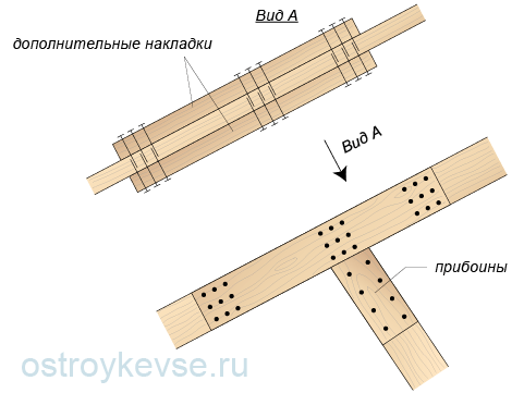 rice. 69. Strengthening the support node by increasing the width of the rafter
 When reconstructing the roof, new rafters are installed under a steeper slope, splicing them with the old (if they have not rotted) wooden-nail cross wall. New rafters can be inserted either on top of the old rafters or below them. The resulting farm provides not only a new slope, but also increased rigidity of the truss structure (Fig. 70). This method allows you not to dismantle the old roof and speeds up work, but it does not increase the under-roof space. If the purpose of changing the slope of the slopes was the construction of the attic, then the volume of the attic will remain the same.
 rice. 70. Strengthening the rafters with a plank-nail truss device
 Sometimes it happens that the end of the rafter leg rots, the support on the Mauerlat turns out to be unreliable, in this case additional struts can be attached to the lower end of the rafter leg, which rest against the same Mauerlat beam or an additional bed (Fig. 71). It is recommended to expand the lower ends of the additional struts - they provide better stability for the rafters. And the struts, supported on an additional bed, can partially reduce the deflection of the rafters in the span between the rafter leg and the Mauerlat. Additional struts are fixed with a nail fight with support in the surfs on the rafters.
 rice. 71. Strengthening the bottom of the rafter leg by installing additional struts
 When raw wood is used in the construction of the roof (with a moisture content of more than 25%) and insufficient ventilation of the cold attic, with high-lying dormers, their small area, or in the absence of attic ventilation, the lower end of the rafter legs or Mauerlat may rot.
Also, rotting can occur if there is no or damage to the vapor barrier and air ducts in the structure of the insulated mansard roof or clogging their ends. Either when moistening the wood of the rafter legs and the mauerlat in roofs of any type during a roof leak, or when there is no waterproofing layer between the wood and the masonry of the wall and moistening the wood from the masonry.
There are several ways to restore and strengthen damaged structures.
1. Application of wooden slips. They are used for single damage to the rafter legs. Reinforcement is carried out by installing reinforcing wooden plates with bolting or nailing. The support of the overlays on the Mauerlat should be the entire end, followed by the installation of a wire twist (Fig. 72).
 rice. 72. Repair of the rafter support unit on the Mauerlat with overlays and prostheses
 2. Use of bar prostheses. They are used for massive damage to the rafter legs. Before starting work, the damaged rafter leg is strengthened on temporary supports, the coating is dismantled and the rotten part of the rafter leg is cut out. The prosthesis is put on the rafter leg and placed on the Mauerlat. The sawn end of the rafter leg rests against the support pad of the prosthesis, which prevents it from slipping. The rigidity of the upper compressed belt of the prosthesis is provided by a strut lattice.
3. The use of overlays based on the beam. This option is used if it is necessary to replace the rotten section of the Mauerlat and the end of the rafter leg (Fig. 73). Before starting work, the rafter leg is strengthened with temporary supports, rotten sections of the leg and Mauerlat are cut out, crutches are hammered into the masonry and a beam 1 m long is laid on them. If the design of the walls and ceiling allows, and most often this is the case, then a meter a piece of bed. Two struts rest against this beam, fixed on nails on both sides of the rafter leg. The crate is supported by a new elongated filly.
 rice. 73. Repair of the rafter support unit in case of damage to the Mauerlat
 With insufficient air exchange in the attic, and as a result, the development of fungal spores and wood decay wooden structures roofs carry out a number of measures to restore ventilation (Fig. 74). In the attic, you should study the nature of the movement of air, determine the air temperature at the upper boundary of the insulation (it should not exceed 2 ° C at any negative outside temperature) and arrange additional ventilation and dormer windows. The cross-sectional area of dormer windows and vents should be 1/300–1/500 of the area attic floor. The width of the ducts should be within 2–2.5 cm. It is necessary to measure and, if necessary, increase to the calculated thickness of the insulation. The caked insulation must be loosened approximately once every five years. For external walls with a width of up to 1 m, its thickness can be increased up to 50% higher than the calculated one. It is necessary to check and, if necessary, restore the vapor barrier under the insulation layer.
 rice. 74. The device of the normal process of air exchange in the attic roof
 Strengthening of other wooden structures, walls, ceilings and foundations can be viewed in a special section of the site.
In principle, I can offer one method that provides for reinforcement without changing the section of the rafters, but whether you like it or not is not for me to decide.
So let's consider the following situation: hanging rafters, which are a triangular arch with a puff or a simple triangular truss (as you like), were made of a beam with a section of 15x5 cm in increments of 1 m. At the same time, the distance between the Mauerlats is the span of the arch l \u003d 6 m Roof pitch - 30°. However, we will not continue to retell the situation, which has been considered in sufficient detail in various articles, for example, but simply say that, according to the calculation, a rafter cross section of 15x10 or 20x5 cm is required, i.e. the available moment of resistance W z = 187.5 cm 3 is almost 2 times less than the required one.
At first glance, the most logical way out of the situation would be to reinforce the existing rafters with exactly the same 15x5 cm beam or install additional pairs of rafters to reduce the rafter spacing. But in both the first and second cases, the cost of reinforcement will be close to the initial cost of installing the truss system.
Meanwhile, there is another way to reduce the value of the required moment of resistance, which I really have never seen in the literature on the calculation of truss systems, but nevertheless quite legitimate from the point of view of theoretical mechanics.
All you need is to change the calculation scheme.
As we know, in the cross section in the middle of a single-span beam with hinged supports, under the action of a uniformly distributed load, a bending moment arises equal to M = ql 2 /8. And for the same beam, but with rigid pinching on the supports, the maximum moment occurs on the supports and is M = ql 2 /12, i.e. 1.5 times less.
Thus, if for the rafter system shown in Figure 462.1.a) (the accepted design scheme is shown in Figure 462.1.b)), we will put the fights between the rafters in the ridge and between the rafters and the puff approximately as shown in Figure 462.1. c), then we can consider the resulting system as an arch made of one rod with rigid pinching on the supports (although this will not be entirely correct).
Figure 462.1. Three-hinged arch and single-rod arch with rigid clamping on supports
Such an arch is statically indeterminate, but we can simplify the problem if we consider the rafters as rigidly clamped inclined beams or as two-span beams on 2 hinged and one rigidly clamped supports. But let's not forget that the normal forces that we defined earlier act on the rods of the arch.
Let's look at the simplest option first:
rafters - inclined single-span beam with rigid pinching
As can be seen from the design diagram shown in Figure 462.1.d), additional rods not only create conditions under which the rafters can be considered as a pinched beam, but also reduce the estimated span length. So the inclined projection of the rafters - a three-hinged arch with a puff, was 3 m. If we place the vertical grips so that in the horizontal projection it will be 0.5 m on each side, then only a decrease in the calculated span by a \u003d 0.5 m or by (1 / 6) will lead to a decrease in torque by 1.44 times, since
(l - l / 6) 2 / l 2 \u003d (25l 2 / 36) / l 2 \u003d 25/36 ≈ 0.7.
Note: the horizontal scramble between the rafters cannot be considered as an additional vertical support.
Thus, the total decrease in the maximum torque will be 1.5 1.44 = 2.16 times, which is quite enough in this case. In numerical terms, the maximum bending moments on the supports of a pinched inclined beam will be:
M c max = ql 2 /12 = 326.1 2.5 2 /12 = 169.844 kgf m or 16984.4 kgf cm
The same moment will be created by a force applied vertically at a distance of 0.5 m from the main support and the component:
P = 169.844/05 = 339.7 kg
This means that for attaching a vertical scramble, it is enough:
The same number of nails can be taken for fastening a horizontal bout if the fastening point is located at a distance of about 5 m from the arch boom in a horizontal projection.
Now it remains to check whether the tightening will withstand the additional load - two concentrated forces P applied at a distance of 0.5 m from each support. According to the design scheme 1.3 from table 1. maximum moment in cross sections tightening will be:
M s \u003d Ra \u003d 339.7 0.5 \u003d 169.844 kgf m \u003d M c max
Then the required moment of resistance for tightening:
W z tr \u003d M / R \u003d 16984.4 / 140 \u003d 121.32 cm 3
Meanwhile, our puff has a cross section of 10x5 cm and, accordingly, the moment of resistance W \u003d bh 2 /6 \u003d 5 10 2 /6 \u003d 83.33 cm 3, i.e. 1.45 times less than required, and this is without taking into account the tensile stresses acting in the cross sections of the tightening.
If you reduce the distance from the support to the vertical grip, then this will only increase the value of the bending moment in the screed, and the number of nails will have to be increased. And if you increase the distance from the support to the vertical scrum, then such a structure can hardly be considered as a rigidly fixed beam.
And here there seems to be no other way out, how to increase the puff, but if the contractions are made not vertical, but at a certain angle to the vertical, for example 35-40 °, then such a contraction will turn on the one hand into a vertical support, and on the other into a horizontal, increasing stretching in puff, while remaining an element that provides rigid pinching of the rafters.
We check. The estimated length of the vertical scramble is:
l in cx = tg30°a = 0.5773 0.5 = 0.2887 m
With an inclination angle of 35 °, the distance a "from the inclined scrum to the place where the vertical scramble would be:
a" \u003d tg35 °l in cx \u003d 0.7 0.2887 \u003d 0.2 m
Then the bending moment acting on the tightening will be:
M h \u003d P (a - a") \u003d 339.7 (0.5 - 0.2) \u003d 101.18 kgf m
The increase in the normal force acting on the tightening will be:
N" \u003d Psina / cosa \u003d 339.7 0.573 / 0.819 \u003d 237.86 kg
Then the maximum normal stresses arising in the cross sections of the tightening, taking into account the difference in the calculated resistances to tension and bending of the wood, will be:
(N + N") / F + M s R p / W z R and \u003d (692.927+ 237.86) / 50 + 10180 101.9 / (83.33 142.7) \u003d 18.61 + 87.26 \u003d 105.9 kg / cm 2\u003e R p\u003d 101.9 kg / cm 2
The necessary conditions for strength are not met by us. However, the excess voltage is less than 4%. Taking into account the accepted reliability factors for the load, such an excess can be considered acceptable, or you can slightly increase the angle of inclination. It's already up to you.
In addition, in reality, the value of the bending moment will be slightly larger, especially if the sheathing boards will rest on the section of the rafter between the inclined scrum and the Mauerlat.
With inclined grips, the number of nails should also be increased:
n = P/(Tcos35°) = 3.88/0.819 = 4.7 exactly 5 nails.
If we consider the rafters as a two-span beam with two hinged and one rigidly clamped support, then the moment on the support - the vertical (or inclined) scrum will be slightly less, and on the rigid support - the arch boom - a little more. However, even such a design scheme is not accurately reflecting the actual operation of the structure.
Nevertheless, a similar calculation can be made, for example, using the method of three moments. Well, for everyone else, advice: add 1-2 nails at the attachment points of the rafters and screeds with contractions.