
Do-it-yourself jet furnace from a gas cylinder. What is a Rocket Furnace? Preparing for the assembly of heating equipment
Dear visitors of the site "", today we will consider detailed instructions for self assembly do-it-yourself camping rocket stove without welding. The jet stove appeared relatively recently and was invented abroad, but in a short period of time it gained people's love and respect in our country, especially among tourists, fishermen and hunters, and of course this stove is distinguished by its economy in consuming firewood and giving off the maximum amount of heat at the output due to jet thrust created by the furnace design itself. With its help, you can cook food in a short time, boil a kettle, which is very important in a hike.
Design jet furnace very simple - it is a vertically located pipe (it is also a body and a chimney) and a firebox adjoining at an angle, divided inside by a plate into two parts (upper for loading firewood, lower for air access to the combustion source) thus a jet draft is formed, hence the loud name « «.
The presented furnace is made with the expectation of compactness, since every gram of cargo and space in a backpack is very important on a hike. For its manufacture, a used helium cylinder was taken (a fire extinguisher can be used), its upper part was sawn off, and a technological hole was sawn on the side for installing the firebox, the design is completely collapsible and all parts are in the stowed position inside the case. We remind you that during its manufacture welding machine is not needed, which simplifies the creation process to the maximum.
Let's look at all the stages of assembling a jet furnace.
materials
- helium tank or used fire extinguisher
- square pipe
- metal perforated plate
- bolts and nuts
- metal sheet 1-2 mm
Tools
- Bulgarian (UShM)
- drill
- pliers
- heat resistant paint can
Step-by-step instructions for creating a camping jet rocket furnace.
To begin with, let's look at the drawing of the domestic Robinson stove, which is also an excellent design, but welded, and the one below is much more versatile and is rightfully considered a camp stove.


 First of all, you need to find a used helium cylinder or an old fire extinguisher, bleed the remaining contents, unscrew the valve and rinse with water, then cut off the upper part, and also make a technological hole in the lower part for installing a square pipe firebox.


 We make a grate from a perforated plate.
  Support legs for firebox.
  We collect all the details into a single whole.
 A pointed metal pin is screwed in the lower part, it is necessary so that when the furnace is installed in its working position, it stands firmly on the ground, and this stake is buried in the ground. In the stowed position, it twists.
  From sheet metal 1-2 mm cut out the comforter.


 By the way, the pin is in the stowed position.
  Also, in addition to the components from the stove, you can put a small supply of dry firewood in the cylinder, which can be very helpful in wet and rainy weather. Just imagine .. you went camping and found you heavy rain, everything around is wet, damp and disgusting, and you calmly take out your camping stove-rocket and make a fire, cook food, boil a kettle and everything is fine with you 😉
  Additionally, a cable was pulled to fix the firebox.
  Here is such a wonderful oven turned out, its advantage is that it is economical, compact, collapsible.
 This design is made without the use of welding, which simplifies the assembly process as much as possible for those people who do not have a welding machine or do not know how to use welding. We hope our material was useful to you. You can also watch a video of the oven in action. Happy viewing!
The simple and cheap design of the rocket stove began its march around the world from North America, where it is still very popular in rural areas to this day. It is known on all continents, including distant Australia. The heating unit captivates amateur enthusiasts with its simplicity and energy efficiency, which, combined with low cost, makes it extremely attractive for home production. Of course, the jet oven big house not to heat, but in the country or in a small garden house, it will be more than appropriate. Surprisingly, but the fact is that only a few people know about this amazing design. And this is in a country where cold weather lasts longer than half a year! Today we will fill this gap and tell you everything we know about the warm and cozy "rocket", including the smallest details of its manufacture by hand and the subtleties of operation.
Reactive oven - what is it

Home heat that comes from a jet stove will not be given by any modern heater
A jet, or, as it is also called, a rocket furnace, in fact, has nothing to do with modern technology. The only thing that makes this heating unit look like a space vehicle is the intense flow of flame and the buzz associated with the wrong mode of operation. Nevertheless, it cannot be said that the rocket oven is a completely technically backward device. Despite the simple design, it uses the most advanced solid fuel combustion methods:
- pyrolytic combustion of gases released during the dry distillation of solid fuels;
- the movement of gaseous products through the channels of the furnace, which does not require forced ejection due to draft.

This is what a simple jet-powered stove looks like
The simplest "rocket" is a curved piece of large diameter pipe. Firewood or other fuel is laid in a short horizontal section and set on fire. At first, the heater works like the most ordinary potbelly stove, but this is only until the temperature of the longer vertical part rises, which acts as a chimney. The red-hot metal contributes to the re-ignition of combustible substances and the appearance of a vacuum at the top of the chimney. By increasing the draft, the flow of air to the firewood increases, which significantly increases the intensity of combustion. In order to achieve even greater efficiency from this original device, the furnace opening is equipped with a door. When the cross section of the air channel decreases, the oxygen supply to the firewood stops and their pyrolytic decomposition into gaseous hydrocarbons begins. But they will not burn completely in such a simple installation - for this it will be necessary to equip a separate zone for afterburning the exhaust gases. By the way, this, as well as the thermal insulation of the chimney, allows more complex “rockets” to successfully compete with other solid fuel units. As for the simplest design we are considering, it is often used for cooking or heating food. All that is required for this is to equip a convenient platform for a pot or kettle on the vertical section of the furnace.
Geography of application of rocket heating units
Being a simple and convenient heating and cooking unit, the rocket stove is widely used both in mobile and stationary versions. Most often it is used:
- for heating residential premises;
- as fruit drying equipment;
- for heating greenhouses;
- to ensure normal working conditions in workshops or garages;
- to maintain a positive temperature in warehouses, utility blocks, etc.
Due to its simplicity, unpretentiousness and reliability, the jet heater enjoys well-deserved respect among fishermen and hunters, rally enthusiasts and survivalists. There is even a special version, the purpose of which is indicated by the name - "Robinson".
Advantages and disadvantages of a rocket oven
Despite the simple design, the rocket oven has a lot of advantages:
- coefficient useful action at the level of the best examples of modern solid fuel heating equipment;
- efficiency - to achieve the required temperature, the jet unit will consume four times less firewood than a traditional oven;
- heating temperature above 1000 °C;
- the possibility of using solid fuels of any type, including dry vegetable waste, cones, needles and shavings;
- completeness of combustion and environmental friendliness - during operation, the temperature of the flame rises so much that soot ignites. The smoke of a rocket stove consists mainly of water vapor and carbon dioxide;
- the possibility of reloading fuel for continuous operation of the heater;
- simplicity and reliability;
- the presence of portable structures designed for mobile use.
The heating unit is not without drawbacks. The operation of the appliance is associated with the risk of penetration into the home carbon monoxide. The stove cannot be used for heating big house, and attempts to install a water heat exchanger in the combustion zone lead to a decrease in thermal power and disruption of the normal operation. The disadvantages include the low aesthetic value of the design, which, however, is a very ambiguous statement, since for lovers of ethnic style, the design of the stove is a real find.
Types of jet heaters. The choice of design for self-production
Craftsmen developed several designs rocket ovens suitable for mobile or stationary use:
- portable units made of metal pipes, cans or buckets;
- jet heaters from a gas cylinder;
- furnaces built of fireclay bricks and metal containers;
- heating heat generators with a bench.
The most difficult to manufacture are structures, the construction of which requires the skills of a bricklayer. Nevertheless, if there are detailed schemes of serial layouts, even a novice home master will cope with this work.
Portable Rocket Oven

Portable rocket furnaces are mass-produced by the industry
Camping options are represented by the simplest designs, which are based on the same pipe bent or welded from separate segments. Improvements have only affected the installation of a partition for arranging an ash pan, in which a slot is made to suck in air. Often, the lower part of the loading chamber is equipped with a grate for supplying air directly to the combustion zone. The opening for laying firewood is equipped with a door, which subsequently regulates the air supply.
The requirements for a mobile design also apply to convenience during cooking, so the upper cut of the chimney must be equipped with a support for metal utensils.
Gas bottle unit
The use of a gas cylinder is the next step in the development of jet heaters. More complex structure allows a significant increase thermal power and efficiency of the furnace. All that is required for the manufacture of the installation is a household gas cylinder or a barrel from fuel and lubricants, pieces of thick-walled steel pipes and a metal sheet 3–5 mm thick.

A rocket stove from a gas cylinder can be used to heat small utility rooms
If there is a piece of steel pipe with thick walls and a diameter of more than 30 cm, a rocket furnace can be made from it. This option will allow you to avoid time-consuming operations associated with dismantling the factory gas tank.
How this design works can be seen in the diagram below. Firewood loaded into the firebox burns due to the air flow through the loading window. Afterburning of combustible gases occurs in a pipe installed inside the cylinder due to the supply of secondary air. To enhance the effect, the inner chamber is insulated, thanks to which it is possible to raise the temperature inside above 1000 ° C. Hot gases in the direction of travel hit the hood and enter the outer chamber, the walls of which act as a heat exchanger. Having given up their energy, the combustion products are discharged through a chimney cut into the lower part on the back of the cylinder.
To create the thrust necessary for the stable operation of the rocket furnace, the top of the chimney is raised by at least 4 m relative to the loading window.
Combined brick and metal barrel rocket stove
The use of fireclay bricks for arranging the firebox and the internal chambers of the jet heater translates the "rocket" into the category of stationary structures. The high heat capacity of the materials used allows you to accumulate heat and give it away for several hours, so such units are often installed in residential premises.

Construction of a furnace with a refractory lining of the working area
Jet stove with bench
Like other solid fuel stoves, the "rocket" has the disadvantage that most of the heat escapes through the chimney. Despite this, the individual advantages of its design make it easy to get rid of this minus. The thing is that the unit was called jet for a reason, but because of the high speed of excision of burning gases. It is precisely this feature of it that can be turned for good by significantly increasing the length of the smoke ducts.

Scheme of a jet furnace with a bench
This idea has found its implementation in massive stationary structures with a couch in the form of a sofa or bed. It is successfully made of brick or rubble stone, decorated with a plastic mass of clay and sawdust. Due to the high heat capacity of the materials used, the stove can retain heat all night, which, combined with high efficiency, makes the heating unit very attractive for installation in residential premises.
When choosing a design for manufacturing at home, it is necessary to take into account the features of its operation. As a hiking option, a mobile unit is chosen - it will be enough to keep warm, dry clothes and cook dinner. In order to heat small technical rooms from time to time, a portable gas cylinder design is used. If you want to heat a small country house or cottage, then there is simply no better option than a jet heating unit with a stove bench.
We build a rocket stove with our own hands
Suggested for self-manufacturing the design is the elite of rocket heaters. After construction, it will delight the owner with comfort and cozy warmth even in the most severe frost for a long time. As you might have guessed, we are talking about a unit with a stove bench. Despite the fact that such a design is the most complex, the diagrams, instructions and descriptions presented by us will allow you to build a furnace in just 2-3 days.
Device and principle of operation
The rocket furnace consists of several chambers and channels. The bunker for loading firewood is made of fireclay bricks and is equipped with an opening for air supply in the lower part. It has a refractory lining and a channel that connects the firebox with a vertical flue (flame tube or riser). A metal barrel is used as the casing of the rocket furnace, inside which an afterburning chamber is laid out with magnesite or fireclay bricks. The heat exchanger of the heating unit is not only a steel tank, but also long horizontal channels of the bench, made of galvanized steel pipes or bricks.

The processes occurring inside a stationary jet furnace resemble the operation of pyrolysis heating units.
There is no need to use refractory materials for the arrangement of heat exchange channels. Enough well-burnt red brick.
The body of the stove and the trestle beds are formed from sandbags, stone or brick fragments and smeared with a clay composition. Good heat storage capacity finishing materials allows the structure to give off heat for several hours after the firewood has completely burned out. To remove the products of combustion, a high chimney is used, which can pass both indoors and outdoors.
The high performance of the "rocket" is explained by the method of fuel combustion, which is more inclined not so much towards direct-flow heating units, but rather towards pyrolysis boilers. The operation of the furnace is accompanied by the active release of gas components, which are afterburned in the riser. The cap helps to reduce the flow rate of hot gases, otherwise they simply would not have time to oxidize. By the way, the heating of the upper part of the flame tube creates a rarefaction at its end, due to which the active combustion of the fuel occurs. The temperature in the riser is so high that even the soot ignites. Nevertheless, at the point of transition from the vertical channel to the horizontal heat exchanger, experts recommend installing an ash pan, equipping its chamber with a small door for periodic maintenance.
Calculation of basic parameters, drawing
There is no need to give the exact dimensions of a rocket stove with a stove bench - its dimensions and configuration completely depend on the characteristics of the room. The presented method of calculating the parameters, based on the use of the proportions of all parts of the rocket furnace, will be quite enough to design a high-performance, efficient unit.
To perform the calculation, it is sufficient to know the diameter D and the height H of the outer heat exchange shell (drum).
- The height of the flame tube is at least 1.3H.
- The gap between the riser and the cap is 0.1–0.15H.
- External clay coating is carried out no higher than 1/3H.
- The thickness of the heat storage layer should be no more than 1/3D.
- The cross section of the flame tube is 0.25–0.3D.
- The height of the ash pan is up to 10% of the vertical dimension of the casing.
- The section of the blower should be 50% less area riser.
- The thickness of the adobe cushion above the heat exchanger is at least 1/4D.
- Chimney height - more than 4 m.
- The length of the horizontal heat exchanger is calculated based on the volume of the drum. In the case of using a standard barrel for fuel and lubricants, it can reach 6–8 m.
As you can see, it is not difficult to determine the dimensions of all elements of the furnace, especially since its design allows some liberties in terms of dimensions and configuration.
For perfectionists and those who are afraid to experiment, here is a drawing of the heating unit, made to scale on a marked sheet of paper. If necessary, it will not be difficult to remove the exact dimensions from it.

Drawing of a stationary jet heating installation
Materials and tools
The construction of a jet furnace does not require any specific devices. Of the power tools in the process of work, only a welding machine and a grinder will be required, and even then just for a few minutes - to separate the barrel lid and configure the heat exchanger pipes. Everything else can also be found in any owner:
- trowel (trowel);
- bushhammer;
- building level and plumb;
- roulette;
- a container for preparing a solution;
- bayonet shovel;
- tamper;
- buckets;
- concrete trowel.
Although the design of the “rocket” is undemanding to materials, some of them will still have to be bought. Here is a list of what will be required during the construction process:
- refractory bricks of any type;
- metal barrel for the manufacture of the casing;
- pipe Ø30–40 cm, which will hold the thermal insulation coating of the vertical channel. You can use a case from an old water heater, a suitable capacity of an industrial receiver or a hydraulic accumulator;
- galvanized steel pipes with a diameter of more than 25 cm, which will be needed as a heat exchanger;
- a steel pipe for arranging a chimney with a diameter of 150 mm and an elbow for its removal by 90 °;
- ash hatch;
- blower door;
- a special heat-resistant mixture for preparing a solution (can be replaced with sand and clay);
- perlite for riser thermal insulation;
- Red brick;
- rubble stone or brick waste;
- sawdust or chaff.
Since the barrel will be embedded in the oven only partially, to increase aesthetic value unit will have to be painted. To do this, you will additionally need a metal brush, a solvent to degrease metal surface, primer and any heat-resistant paint.
Site selection and other preparations
When determining the construction site, one should take into account the requirements that apply to all designs of solid fuel open flame furnaces:
- the area of \u200b\u200bthe room in which it is planned to install a jet heater with a sunbed should be at least 16 m 2;
- the absence of logs (floor beams) under the furnace body will greatly simplify installation;
- above the hearth there should not be wooden rafters and ceilings;
- if part of the chimney passes through the ceiling, then the stove is installed closer to the central part of the house. In this case, the pipe can be fixed near the ridge;
- you should not install a heating structure close to the outer contour of the building - precious heat will go outside. It is better to attach the unit to one of the internal walls;
- it is not recommended to build a reactive device near wooden walls and partitions. In this case, choose a separate location.
It is also important how convenient it will be to kindle a rocket stove and throw firewood into it. To do this, the firebox is placed towards the entrance, providing at least 1 m of free space in front of it.

One of the many options for installing the stove in the middle of the room
AT small room it is convenient to place the rocket furnace in the corner, orienting the hopper in one direction, and the lounger in the other.
Having chosen a place, they begin to prepare it for future construction. If the room has a wooden floor, then that part of it that will be under the stove is removed. After that, a shallow pit is dug, the bottom of which is compacted with a rammer.
In addition, it is necessary to prepare a metal barrel for installation. To do this, cut off its cover along the contour. In this case, a part of the thickening in the form of a metal hoop is left to ensure the rigidity of the base of the casing. Most likely, the container from under the fuel and lubricants will be dirty and rusty, so it is better to clean it before installation.
The last thing to do before starting construction is to prepare the solution. It is best to use a special heat-resistant composition that can be bought at hardware stores, but you can get by with a simple mixture of sand and clay in a ratio of 1:1 or 1:2, depending on the fat content of the latter. Water will be needed up to ¼ of the volume of dry components - the output should be a composition resembling thick sour cream.
Instructions for the progress of work
As already mentioned, in order to make a rocket stove with a bench, it will take much more effort and time than in the manufacture of a metal unit. Facilitate the task and reduce time will help step-by-step instruction with illustrations of all stages of construction.
- The place where the firebox will be formed is deepened by 10 cm and laid out with refractory bricks, after which the formwork is installed along the contour of the furnace. To strengthen the foundation, it is necessary to install reinforcement from construction mesh, reinforcement Ø10–20 mm or scraps of metal pipes and corners.

Formwork arrangement
- The base of the working chamber is laid out according to the level.

The base of the loading chamber is laid out with refractory bricks
- Fill the structure with concrete. Further work can be started immediately after setting the solution. As a rule, one day is enough for this.

Foundation pouring
- From refractory bricks laid in a continuous order, form the base of the jet furnace and the combustion chamber.

Rocket oven base
- Several rows of masonry raise the side walls of the structure.

The walls are formed using fireclay bricks installed on the edge
- Equip the lower channel of the heat-generating rocket.
- The combustion chamber is covered with a row of bricks laid across in such a way as to leave open two openings - the firebox and the riser (vertical channel).

Method of overlapping the horizontal part of the working chamber
- Prepare for installation of the old body from the boiler accumulative type. To do this, the device is cut on both sides to get a large diameter pipe.

Furnace parts prepared for installation
- The lower part of the fuel tank is equipped with a flange, which will include a horizontal heat exchanger pipe. Welds must be continuous to ensure tightness and, accordingly, the safety of the structure.

Installation of the lower branch pipe is carried out by welding
- After the outlet pipe is cut into the barrel, it is cleaned of rust, covered with a primer and several layers of heat-resistant paint.
- A side outlet is welded to the horizontal chimney, which acts as an ash pan. To clean it, the channel is equipped with a sealed flange.
- A fire tube is laid out of fireclay bricks. The shape of its internal channel is a square with a side of 18 cm. During operation, the vertical position of the structure must be controlled using a plumb line or building level.

The height of the vertical channel depends on the dimensions of the outer drum
- A casing is installed on the flame tube, after which the gaps between the metal container and the walls of the vertical channel are filled with perlite. To avoid spillage of thermal insulation on the floor, the bottom of the riser is carefully sealed with a clay mixture.

Riser insulation method
- The cap of the firebox is made. In its capacity, you can use the cut off part of the water heater, providing it with a convenient handle.
- With the help of brick or stone masonry, the furnace body is formed. Sandbags placed at the base of the vertical channel can also be used for this purpose.

Furnace body can be lined with sandbags
Unpretentious spring appearance is hidden with the help of adobe coating. For its manufacture, up to 50% of large sawdust or chaff (chaff) is introduced into the clay solution.

Coating of the furnace body
Additives in the clay mix perform the same role as crushed stone in concrete. They are needed so that during drying and subsequent work with variable thermal loads, the surface of the furnace does not crack.
- Perlite backfill on top also needs to be sealed with a coating.
- Form the front of the furnace. To do this, in any suitable way (brick or masonry, sandbags, adobe), lay out the contour of the furnace. Inner part fill with crushed stone, and the top is given the desired shape using an adobe mixture.
- An outer casing from a metal barrel is installed on the prepared base, orienting the container with the lower pipe towards the bed. The bottom of the container is sealed with clay.

Installation of a casing - a metal barrel
- Using a corrugated pipe, a channel is led to the firebox, which connects the furnace with the external atmosphere. If it is not installed, then the stove will consume warm air from the room, which will be replaced by cold masses coming from outside. From the side of the firebox, the channel will need to be blocked as soon as the firewood is completely burned out. This will not allow air from the street to penetrate into the heat exchange channels.

Air supply duct outside the building
- To check the operation of the rocket furnace, the first kindling is carried out, during which they make sure that the gases freely exit into the horizontal chimney.
- Heat exchanger pipes are connected to the lower branch pipe, which are installed on a base formed of red brick.
- Perform chimney installation. All joints of the parts of the horizontal and vertical channels are sealed with asbestos cord and refractory coating.
- Using the same method as in the manufacture of the furnace body, give the required configuration to the bench.

Fully formed oven with bench
- The barrel can be completely covered with adobe, leaving only a horizontal platform open, which is convenient to use for heating food.
- The chimney brought out is equipped with a condensate and tar trap, and the upper cut is protected from precipitation with a cap.

The outer part of the chimney is supplied with a trap for liquid substances
Tests of the rocket furnace are carried out only after the adobe coating has completely dried. Otherwise, cracking of the decorative coating is possible.

View of the finished rocket stove with a stove bench
For safe operation rocket furnace, the room must be equipped with carbon monoxide sensors.
Modernization of the rocket heat generator
To expand the scope of reactive heating stoves, they are being finalized, increasing the convenience and versatility of the design. A platform intended for cooking is often replaced in mobile structures with a full-fledged stove. It is convenient to use such a hob in your own backyard for household purposes - for cooking food for pets or during the preservation of blanks for the winter. A feature of this type of rocket furnace is a wide and flat horizontal channel into which hot gases are directed from the nozzle. Passing under the surface of the stove, they heat it red-hot, after which they go into a vertical chimney. Comfortable legs give stability to the structure, and the original shape allows the unit to be used as a stand or table when it is not used for its intended purpose.

A jet stove with a stove is a necessary thing in a suburban area
A liquid heat exchanger cannot be installed in the flame tube of a jet furnace, but this does not mean that it cannot be used as a heat generator for a water heating system. To do this, the "rocket" is equipped with a kind of contour of radiator plates, which create a kind of labyrinth in the afterburning zone. Due to their heating, heat is removed from the afterburner to the water jacket. The efficiency of the unit depends on the area and heat capacity of the plates, so they are made in the form of massive metal strips with an area of up to ¾ of the cross section of the flame channel. It must be said that such a heat exchanger is best used to obtain hot water using the rocket oven itself in the traditional way.

Scheme of a rocket assembly equipped with a water circuit
The rocket stove with a convector has an original design. To increase heat transfer, vertical tubes are mounted on the surface of the outer casing, which perform the same role as the air channels of the buleryan. Cold air is trapped at the bottom of the tube heat exchangers and heated up as it moves up. This ensures forced convection, which further increases the thermal efficiency of the installation.

Shell of the rocket heat generator equipped with a convector
Features of using jet furnaces
As a long-burning system, the rocket stove requires preheating before operation. As a rule, no one complies with this requirement in mobile installations - they consume little fuel, and the potbelly stove itself is most often used according to the principle "it works, and that's okay." In stationary structures, it is extremely important to warm up the furnace before starting up, since with a cold flame tube, there can be no question of any afterburning. Firewood will burn without giving off heat, and the chimney will very quickly become covered with soot, tar and creosote.
The furnace is heated using chips, paper or shavings, which are loaded into the firebox and set on fire. The output to the operating mode is judged by the buzz in the flame channel. A strong sound indicates inefficient operation of the unit. As soon as the rumble begins to subside, it is necessary to start laying the main fuel. The blower in the first 10-15 minutes should be completely open. Then the air supply is reduced, focusing on the sound of the furnace - it should “rustle” or “whisper”. After the firewood burns out, the air channel of the firebox is covered to prevent heat from escaping from the room. Once every 2-3 days, the ash is removed, for which they use a metal scoop and a poker.
Maintenance of the jet furnace is carried out no more than once a season. To do this, open the ash pan door, through which soot residues are removed. Clean if necessary smoke channel using the hatch of its trap for this. I must say that the correct operation of the jet heater never leads to smoke in the room. All that is required for this from the owner is to follow the recommendations for using the "rocket" and not neglect the safety rules.
Do-it-yourself rocket stove: the subtleties and nuances of construction (video)
Unique specifications, almost zero cost and availability of materials for construction cover all the shortcomings of the jet furnace. If you wish, you can build a full-fledged heater over the weekend, including arranging a comfortable bed. "Rocket" is also convenient because it does not require a highly qualified stove-maker, but in external design allows the implementation of even the most unusual design intent.
Now there are many stoves that use firewood as fuel. A special place among them is occupied by the so-called jet (rocket) units, which have specific features that are indispensable in certain operating conditions. Let's talk about them.
The rocket is a real marvelous unit!
The rocket stove is a heating and cooking system that operates on wood, is famous for its high technical performance and has a simple design. The principle of operation of such a long-burning unit is based on the fact that the gases formed during the combustion of fuel enter a special bell, in which they are completely burned. Due to this, the temperature indicators of the stove increase significantly, and the pressure value decreases. Moreover, soot is not formed in the jet heating system.
The cycles of combustion of heated gases are repeated constantly (while the furnace is being heated). This causes the system to go into maximum thrust mode. Its specific value is determined by the features of a home-made unit. If the heating device is assembled really correctly, the temperature in its hood can reach 1200 ° C. In this case, all the fuel used is burned without residue. It is also important that the heated cap is allowed to be used as a hob. On it you can dry fruits, heat water, cook food.
Initially, the stove we are interested in was designed for use in difficult (for example, camping) conditions. Because of this, its design put forward special requirements. The result is a unique unit that:
- makes it possible to cook in areas where there is no gas and electricity;
- qualitatively heats the room;
- saves heat for 6-8 hours (minimum) after burning firewood;
- has a high efficiency;
- quite safe to use.
In addition, the rocket has a design that allows you to report a new portion of firewood into the furnace without stopping the combustion process. The operation of the unit with similar capabilities, of course, is to the liking of any person. This determines the high popularity of the described heating systems both among outdoor enthusiasts and among ordinary summer residents who need unpretentious and efficient stoves.
An important point. If you plan to create the simplest jet unit with your own hands, it can only be heated with dry wood. Wet wood can cause backdraft. However, it is not recommended to kindle more complex rockets with wet wood, since they will not be able to provide the high temperature required for burning heated gases.
The described heating devices must not be left unattended. Melted the stove, wait until the fuel burns out completely. Another drawback of rocket equipment is the impossibility of heating private baths with it (in particular, their steam rooms). This is due to the fact that the jet unit gives very little infrared heat, which is exactly what is required for taking bath procedures. Missiles, perhaps, have no other disadvantages.
Types of jet heating installations - what do you need?
The simplest rockets are made from almost any tin can. A portable stove can be made from a bucket, a can of paint, and so on. Such systems are ideal for a picnic in nature, they are often used on construction sites. Simple stoves are not suitable for space heating. They are used exclusively for cooking, heating water. A rocket made from a bucket can be fired with a small torch, dry cones and foliage, bunches of branches. In such a stove, combustion products do not have time to form combustible wood gas. They immediately go into the chimney.
More complex heating structures are created from an old gas cylinder or from a metal barrel and brick. These furnaces are necessarily equipped with a riser to increase traction and a horizontally located smoke path. There are also rockets made entirely of bricks. They can be equipped with several chimneys at once and are used for heating large rooms and floor heating. And if you wish, it’s really possible to build even a full-fledged stove-bed.

We will tell you how to independently make all these types of reactive devices for heating. And let's start our master class with the simplest - with the manufacture of an elementary garden-camping stove from two tin containers (buckets, cans). In addition to them, we need steel clamps with a section of 10 cm, metal corners, a grinder, a stainless steel chimney pipe, metal scissors, gravel. The scheme of work will be as follows:
- 1. We take two buckets. From a container of a smaller volume (diameter) we make a cover for our rocket. Cut a hole in the bucket. It is necessary for the organization of the chimney.
- 2. In a larger bucket, cut out another hole at the bottom. We will connect the firebox to it. We carry out all operations with scissors for metal, bending the resulting petals (pieces of tin) inward.
- 3. We construct a forward flow from the pipe and corners. We insert it into the bucket, and then, using a clamp, we connect it with curved petals.
- 4. We fill the space between the forward flow and the body of the heating device with gravel. This building material will play the role of a heat accumulator and at the same time a heat insulator.
- 5. We put the second bucket on the stove.
- 6. We bend a small burner from the wire, on which it will be possible to install dishes with water and food.
It is advisable to paint a portable rocket with any paint with high level heat resistance. After drying, we can use an elementary cooking stove. Note! The ignition of the rocket is carried out through a branch pipe extending from the forward flow.
A stove made of barrels and bricks - both cooks and heats!
The construction of a stationary rocket launcher requires significantly more money and time. We prepare the following materials and tools: a metal chimney pipe, a red (necessarily heat-resistant) brick, a shovel, an old barbecue, a metal brush, a trowel, cement and sand (it is better to immediately buy a mixture of these materials ready for use), reinforcing bars, a little perlite, adobe and expanded clay, heat-resistant paint, a barrel of 200 liters. We proceed to the construction of a brick oven and a metal barrel:
- 1. We dig a hole in the floor with a depth of 0.3-0.5 m. We will hide a horizontal chimney in it, without which the rocket launcher will not work.
- 2. We burn a 200-liter barrel, thoroughly clean it. We mount a flange in the tank that will connect it to the chimney. After that, we apply several layers of heat-resistant paint to the container. We use the barrel prepared in this way as a cap for the heating unit.
- 3. We equip the foundation. We make a simple formwork from boards, deepen 2-3 bricks into the ground at the installation site of the furnace. We place reinforcing bars on top. Then we lay bricks in the lower part of the combustion chamber (around the entire perimeter). We fill the structure with a cement-sand mortar.
After the fill dries, we proceed to the masonry. It is done with . We bring the first tier of masonry up. We need to leave only a hole for the firebox. On the second line we form a channel (lower) of the heating structure. It should be blocked on the third tier, and in such a way that we have two holes left. One of them is intended for the vertical channel, the second - directly for the combustion chamber.
Next, we mount a tee in the barrel to clean the chimney. It is not necessary to install it, but it is desirable if you plan to use the stove for a long time. After that, we put a vertical channel. The rising section of the structure (we take its diameter of about 18 cm) is laid out using the "boot" technology. Then we put on the old water heater on the ascending part of the furnace. All voids that remain after this operation are filled with perlite.
Now we cover the base of the casing of the rocket unit with clay and surround the base of our structure with sandbags. All remaining free areas are filled with expanded clay. We connect the chimney pipe to the structure, turn the casing barrel over and pull it onto the rising part of the stove. The final work is lining the chimney with sand in bags and filling them with expanded clay. Then we give the structure the required shape with the help of clay (fireclay), mount a barbecue grill in the neck of a home-made rocket and cover it with a lid.
The last step is to seal the existing seams on the furnace. In principle, we can already do a trial run of our design. But experts advise additionally bringing a separate air duct from the street to the stove. It is important. A heating rocket needs a lot of air to function properly. In the room it will not be enough. A street duct is guaranteed to solve this problem.
Rocket heating from a cylinder - let's work with a welding machine
For the construction of the rocket, we choose a heat-resistant and non-explosive cylinder. An all-metal 50-liter tank in which propane is stored is optimal for these purposes. This balloon has standard sizes: height - 85 cm and cross section - 30 cm.
Such parameters are ideal for self-production of the furnace. The modest size and small weight of the cylinder do not make it difficult to work with it. At the same time, it is allowed to burn any wood fuel in the finished rocket. You can also take propane cylinders for 27 or 12 liters. They make compact portable stoves. But the power indicators of such devices are small. It is not advisable to use them for heating rooms, country houses.

For the construction of the furnace, in addition to the cylinder, you will need:
- pipes made of steel with a cross section of 15, 7 and 10 cm (the first two will go to the organization of a vertical internal channel, the third - to the chimney);
- profile tubular product 15x15 cm (we will make a loading compartment and a firebox from it);
- 3 mm thick sheet of metal;
- dense (100 or more kg / cubic meter) basalt fiber (it will serve as a heat-insulating material).
On the Internet there are various drawings for creating a stove from a balloon. We propose to follow this scheme.

The algorithm for manufacturing a rocket balloon installation is simple. First, we bleed all the gas from the tank. Then we unscrew the valve, fill the tank with water (up to the top) and cut off its upper part along the seam. We cut out the windows on the two sides of the gas cylinder that are required to connect the chimney and install the fuel chamber.
After that, we insert the profile tubular product into the container, connect it to the channel (vertical). The latter is taken out through the bottom of the tank. Next, we do everything necessary actions, focusing on the presented drawing, as well as on the video that we offer home craftsmen for review.
At the end of the work, we weld the cut off part of the container in its place, analyze all the resulting seams for permeability. Uncontrolled entry of air into the structure must not be allowed. If the seams are reliable, we connect a chimney to a home-made system. We weld the legs to the bottom of the rocket balloon. We install the stove on a steel sheet with parameters of 1.5x1 m. The unit is ready for use!
Stove-couch - for lovers of special comfort
The heating unit with a place to sleep and rest is equipped with a special heat exchanger. Its channels are interconnected. They are made from non-flammable materials. The heat exchanger is installed under the bed plane. The design of such a furnace is very thoughtful and relatively complex. The bed itself is a surface made of brick or stone and clay. When the stove burns, the heated gas moves through the heat exchange channels, gives up heat, and then is removed through the smoke duct outside the house. The height of the chimney is made within 3–3.5 m. The stove is mounted at the edge of the bench (on one side). In most cases, it is equipped with a cooking surface. Detail drawing this system is shown below.
.jpg)
Elements of the furnace in the diagram:
- blower - 1a;
- fuel bunker - 1b;
- channel for secondary air - 1v;
- flame tube - 1g;
- riser (primary chimney) - 1d.
The fuel chamber is equipped with a blind cover, the blower is equipped with a special regulator for adjusting the amount of air supplied. The flame tube has a length of 15–20 cm. The secondary air channel is necessary for the complete combustion of gases. The cross section of the riser is 7–10 cm. A chimney with a diameter of 10 cm is recommended for cases where we want to get the most rocket power. A riser with a cross section of 7 cm provides an optimal indicator of the efficiency of the stove. The flame tube and the primary chimney need high-quality thermal insulation.
We will make the rocket body from a gas cylinder, although a metal barrel can also be used. Under the housing cover (2a), the primary chimney supplies heated air, and the heated gases leaving the riser heat the cooking device (2b). Other body elements:
- lower part (2d);
- heat exchange channels (2d);
- shell - metal insulation of the chimney (2c);
- exit to the cleaning chamber (2e).

The flue pipe must be completely sealed throughout. At a height of 1/3 from the upper end of the drum (body), the gases already have a low temperature. They get cold. Approximately from the specified height, the rocket bed is lined (to the floor). This process is understood as the thermal insulation of the furnace. special formulations. The second cleaning chamber in the scheme (3a) is needed to remove carbon deposits from the hog (4) - the heat exchanger. It must be equipped with a sealed door (3b). Now that we have dealt with the design of the couch, we can proceed to its construction.
Building a rocket with a place to sleep - the first steps are the most important!
Before starting work, we knead all the necessary compositions:
- Kiln clay (designation 5b in the diagram), which is connected to crushed stone. This composition plays the role of the main heat insulator.
- Saman (5a). It is a composition of straw and any clay at hand, diluted with water to a relatively thick consistency.
- Seeded sand (5g).
- Heat-resistant lining (5v). It is made from equal parts fireclay sand and clay.
- Clay of medium fat content (5d). It is used for laying rockets.
We make a bed for our couch. In fact, we need to knock down high-strength shields under the stove bench and directly under the stove. We make the frame of the structures from wooden bars 10x10 cm. We make the cells of the frame with dimensions of 60x120 cm (for the bed) and 60x90 cm (for the heating installation). Then we sheathe the resulting 4-centimeter skeleton. And the facade of the couch can be finished later with sheets of drywall.
It is advisable to treat wood products with Biocide before installation, and then apply two layers of an aqueous emulsion on them.
We lay on the floor, where we will put a heating rocket, basalt cardboard 4 mm thick. In shape and geometric parameters, it must be similar to the characteristics of the bed. We install an iron roofing sheet on top of the basalt lining. In front of the firebox, it will come out from under the unit by about 25 cm. We mount the bed made earlier on the place prepared for it. On the wall at a height of 13 cm above the level of the bench (at one of its ends), we punch a hole. It is necessary for the device of the chimney.

The next stage is the installation of formwork along the perimeter of the bed and pouring the installed structure with adobe. The surface of the mixture is carefully leveled using the rule. We wait 14-20 days until the adobe hardens. During this time, it is possible to make the body of the heating structure from a gas cylinder according to the previously described scheme. The furnace parts of the rocket (blower, flame channel, chamber) are welded into a single structure with a gas container and coated with a heat-resistant lining. Important! We apply the composition in a continuous layer only below. We do not process the upper part and sides of the structure with a solution.
Next, we mount another formwork under the area where the rocket will stand. It will allow us to make a heat-resistant thermal protection of the stove. The height of the formwork structure is about 10 cm. We fill it with a mixture of crushed stone and oven clay. Then, one by one, we do:
- 1. Shell. We bend it from a sheet of steel or use a finished pipe with a section of 15–20 cm.
- 2. Furnace structure.
- 3. Cleaning chamber. This element is made of 1.5 mm galvanized steel. On the side, we cut an opening with a section of 16–18 cm. A chimney will subsequently enter it.
Completion of work - a warm couch will turn out well!
We put the drum from the gas cylinder on the primary chimney. At the bottom of the installed body, lay out the oven clay, forming an inclined surface (about 7 °) with a spatula, which is directed to the window of the cleaning compartment. Then we put a metal round timber on the chimney. It should be pressed into the clay composition. Then we stretch the shell on the riser and coat it with clay of medium fat content. The next steps are:
- 1. We line the chimney from the inside. We use sand. It should be covered in separate layers. Each of them is wetted and rammed. The total number of layers is 7. We put 5 cm of medium-fat clay on top of the sand.
- 2. We put a cleaning box, coating its bottom and side surfaces with clay. We mount the opening of the transition channel in the opening of the drum, press it as hard as possible. All remaining gaps are sealed with clay. It is necessary to achieve complete tightness of this stove assembly.
- 3. Along the contour (external) of the bed, we mount the next formwork. It should rise above the edge of the hole for the hog by about 9 cm. Fill the formwork with adobe mixture.
- 4. We stretch the corrugated pipe along the entire length of the rocket bed. We connect one end of the corrugated product to the cleaning department.
- 5. We lay the fixed corrugated pipe in a spiral and insert its second end into the chimney outlet opening, fixing the junction with a clay composition.
- 6. We process the burs along the entire length with a solution of adobe, compact this coating.
- 7. We fix the housing covers and the cleaning chamber with bolts, under which we install rubber gaskets.
- 8. We coat the drum with adobe (we do not touch only the upper part) with a layer of about 10 cm.
After about 17 days, the adobe will dry out. We will be able to remove the formwork, apply special enamel to the drum, which can withstand heating up to 750 °C. Then experts advise to treat the adobe surface with acrylic-based varnish (preferably in two layers). Such a coating will protect the structure from moisture and make the stove outwardly very attractive.
The heated bed is done. We test our facility before the start of its full operation. Verification is elementary. We put some paper in the firebox, set it on fire, and monitor the behavior of the rocket. If everything is fine - there are no frightening sounds, we put firewood. After a while, the unit will begin to hum. At this point, we close the blower of the furnace. We wait. When the buzz is replaced by a gentle whisper (the soft sound of a working stove), open the blower a little. Next, we use the heating installation for its intended purpose.
A simple heating device, which is not much inferior to a potbelly stove in popularity, is a rocket stove. It works on wood, and the design scheme is so simple that it is possible to manufacture it on your own. The stove can also be made economical - many people think that looking like a potbelly stove means the voracity of the combustion chamber, but no. There are schemes that work on smoldering wood (pyrolysis), which means that they are economical with the same efficiency.
Why rocket and why jet
Such a stove is often called a "rocket", but not because the wood in it burns with high speed, and because of the shape of the structure, the traditional version of the rocket stove is made from two pieces of iron pipes welded to each other. The unit resembles a rocket in a child's drawing. The use of a simplified form allows you to make it in less than a day. The adjective “reactive” is also used for the stove, but also not because of the speed of fuel combustion, but because of the characteristics of combustion - at a certain stage of air supply to the firebox, it starts to hum strongly, as if turbocharging of the nozzles in the engine is turned on.
Furnace humming is an inefficient and consumable combustion mode. During normal operation, it emits a quiet rustle.

Any owner of a country or country house has in the workshop at least minimum set carpentry, locksmith and automotive repair tools. So they will help in the manufacture of a miracle rocket, plus blueprints and a minimum supply of materials: pipes or metal boxes, a sheet of iron and - in the construction of a stationary version - brick and mortar on clay. Now it becomes clear that the jet stove is made portable or stationary, for example, for heating a house or a bath. 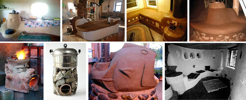
If a stationary jet stove will heat the house, then it is located along the outer wall. Properly designed and equipped, it can heat a house up to 50m2. Also, the oven is installed in an open area - on personal plot, and used as a summer option for cooking.
How does a rocket stove work?
The device is the simplest - two principles of fuel combustion borrowed from other furnaces:
- The natural circulation of hot gases and smoke through the channels of the stove is a standard solution, as in a potbelly stove.
- Afterburning of unburned gases (pyrolysis) with limited access of oxygen to the combustion chamber.
The scheme of the simplest jet stove, which is intended only for cooking, uses the natural combustion of firewood - in an open chamber it is impossible to create conditions for maintaining the pyrolysis reaction and afterburning unburned gases.
Let's consider a simple design of a direct burning rocket stove, which is traditionally installed in the yard in an open area. It can quickly heat water or cook dinner for the family on vacation. From the figure below, it becomes clear that such a sample will require two segments of a cylindrical or rectangular iron pipe, which are interconnected by welding at an angle of 90 0 .

A horizontal segment of a metal box acts as a combustion chamber - firewood is laid there. Also, fuel loading can be organized vertically - add a vertical iron cylinder on top of a horizontal pipe for loading firewood. Thus, a structure of three pipes or boxes will be obtained, the lowest of which (horizontal) will work as a firebox. In a stationary scheme, the simplest stove design often uses red brick, which is placed on clay mortar.
The efficiency of the design cannot be called satisfactory, so the craftsmen figured out how to increase the efficiency of its work. Additional element - another pipe larger diameter(as you can see, all materials are available and cheap), in which the main pipe of the riser stove (primary chimney) is installed. This increases the overall heating and the duration of heat retention. 
On the diagram:
- Outer body.
- A pipe that serves as a firebox.
- Channel for air outlet to the combustion chamber.
- Insulated area between hull and riser. The same ash can serve as a heater.
How to heat
The Robinson jet stove is heated according to the principle of kindling a fire - paper, hay, straw or other quickly combustible material is laid first, then small chips or large chips. The last logs are laid in the size of the firebox. Hot combustion products rise along the vertical pipe (2) and go outside. On the open end of the pipe (2) you can put a pot or a tank of water.
In order for the fuel to burn continuously and actively, it is necessary to provide a gap between the outlet pipe (2) and a pot of water using a special lattice metal stand.
The diagram below shows a simple device with a door on the fuel loading hole. Air draft is formed due to the presence of a special channel formed by the lower surface of the furnace and an iron plate welded 8-10 mm from the combustion chamber. This design will forcibly pump air even if the door closes completely. It can be seen from the diagram that the design is also designed for operation in the pyrolysis mode, while a constant flow of a “secondary” air jet will burn out the exhaust gases. But in order for the afterburning to take place at 100%, it is necessary to equip the thermal insulation of the secondary chamber in which the gas burns out in order to provide the necessary temperature indicators for pyrolysis.
On the diagram:
- Forced channel for blowing air with the furnace door closed.
- Area of active combustion.
- burnt gases.

The improved scheme provides not only the possibility of heating the surrounding space, but also cooking, for which the upper hob. In total: to the simplest version of the “rocket”, you can add an outer case, which will additionally heat the room, the furnace door, blowing air to maintain the pyrolysis mode and a stove for cooking food. This scheme can already be implemented in the house itself, and not in the yard, since the chimney pipe is brought out. Such a minor upgrade significantly increases the efficiency of the model. So, a do-it-yourself rocket stove, the drawings of which are presented below, has the following capabilities:
- Due to the embedding of the outer casing from a larger diameter pipe and its insulation, which creates a thermal insulation layer for the riser, as well as the ability to hermetically close the top pipe hot air cool down much longer.
- A separate blowing channel has been added in the lower section of the stove, which allows organizing pyrolysis combustion.
- The chimney in such a scheme is recommended to be placed not vertically at the top, but from the bottom at the back of the case, which will allow organizing additional circulation of hot streams through the internal channels of the stove, ensuring rapid heating of the hob and the entire insulated case.

In the firebox (1), the fuel does not burn completely (2), since the air supply is not carried out in in full, is the "A" mode, which can be controlled by the damper (3). Hot, but not burnt out from pyrolysis, gases are fed into the end section of the fire channel (5), in which they are burned. Afterburning provides high-quality thermal insulation and a constant flow of "secondary" air in the "B" mode through the channel (4).
The hot stream then enters the inner riser (7), rises up to the cooking plate (10) and heats it up. Further, hot air enters the volume (6) between the outer and inner pipes, insulated with a layer of ash (4, 9), heats the furnace body, which gives off heat to the room. Finally, the cooled air descends to enter the chimney (11) and exit.
Consistently high temperature in the riser (7) provides maximum heat transfer and creates conditions for complete combustion of gases due to the placement of the riser in the pipe bigger size– shell (8). The free space is filled with ash or other heat-resistant substance (9) for lining - it can also be a solution of ordinary clay with sand in proportions of 1:3. 
The palm of popularity belongs to the industrial model "Robinson" - this is a simple but reliable design. Having such a mobile stove, you can quickly cook food or heat water in the country or on a hike. Structurally, this is an inverted L-shaped pipe, as shown in the diagrams below. 
Firewood is laid in the horizontal section of the fuel receiver, and ignition is carried out from the side from which the vertical pipe enters. In the L-shaped pipe, due to the pressure difference between hot and cold air, draft arises, and the intensity of combustion will only increase as the furnace body heats up. The air supply is controlled by a damper. 
The furnace works on the principle of energy consumption of the natural flow of hot gases. It turns out a closed cycle: as the temperature rises, the fuel begins to burn more actively and the chamber and hob heat up faster. As a result, "Robinson" is able to heat 10 liters of water in 10 minutes, if you put the tank on an already warm surface. The diagram shows that the hob in the "Robinson" has a thick heat-insulating layer, which allows you to put large diameter chocks into the firebox.
Stationary oven
Stationary models have a cap to keep the heat in the room longer. In such a stove, fuel combustion occurs according to a different scenario. The beginning of the process of burning wood is the same - the air supply is limited. This causes the release of pyrolysis gases, which are afterburned in the lower section of the vertical pipe or duct, where the secondary air is supplied separately. 
The hot gas, once at the top, begins to cool and descends into the free inter-chamber volume, and then into the chimney. It happens like this:
- Gravitational forces cause the colder, and therefore heavier, burnt gases to rush down, where they enter the chimney.
- This is facilitated by the constantly maintained pressure from the firewood and the consistently high temperature of the gases.
- Natural draft in the chimney.
All this creates effective conditions for burning firewood and it becomes possible to attach a smoke channel with arbitrary geometry to the “rocket”. Basically, long and complex chimneys are needed in order to better heat the room. 
The main disadvantage of all solid fuel stoves is the inability to keep most of the heat in the house. But positive traits allow you to level the negative points - a high rate of gas outlet allows you to organize complex vertical or horizontal chimneys with several channels. The implementation of this principle in practice is the Russian stove. In a jet furnace with a horizontal multi-channel chimney, it is also possible to equip a warm bench, as shown in the diagram below. 
A jet rocket stove is a variant of home heating, which is cheaper only for nothing. A person familiar with the basics of construction can fold a combined brick oven in a design suitable for any home interior. The main task of ennobling the appearance will be decorating the iron cap and the lid of the firebox - everything else will not be visible. 
Combined brick-metal barrel oven
It is stationary, because the structure cannot be moved. A fuel chamber and a chimney are laid out of fireclay bricks, valves and doors are made of metal. The brick gives off heat very slowly, so the room will be warmed for a long time. 
High efficiency- not a hobby of such models, but good heat transfer can be achieved by adjusting the air supply to the chamber, without trying to enter the combustion mode, in which the stove begins to “roar” and “buzz”. 
In order to somehow minimize heat losses during the operation of this simple design, many craftsmen build a water circuit into the oven and connect a hot water tank. Also, the construction of a stove bench with a multi-channel horizontal chimney contributes to the preservation of heat in the room. Negative qualities of "rocket" models that cannot be minimized or removed:
- It is necessary to constantly monitor and adjust the thrust - there are no automation devices.
- Every 2-3 hours you need to load a new portion of firewood.
- The iron cap heats up to dangerous temperatures.
The simplest and cheap option- model "Robinson", which is in the drawing below. For its manufacture, you need trimming pipes or a rectangular profile box, metal corners for legs, a welding machine. Its dimensions are selected based on the dimensions of the blanks. The main thing is to adhere to the principle of action, not size. 
For homemade design often take gas cylinders or barrels of 200 liters - thick walls and suitable size as close as possible to what was intended. Both those and others are used to make the outer case, and the internal elements are made from pipes of a smaller diameter or are brought out with bricks - halves, quarters or whole.
There is no general formula for calculating heat transfer for all models of a rocket stove, so the option of using ready-made calculations based on the principle of similarity of circuits is quite suitable. The main thing is that the size of the future "rocket" should at least approximately correspond to the volume of the heated room. For example, a gas cylinder will do for a garage, for country house- a two-hundred-liter barrel. An approximate selection of internal elements is shown in the diagram below. 
Iron bottle stove
- Cylinder - gas, oxygen, from under carbon dioxide.
- Pipe ≥ 150 mm for fuel and loading chambers.
- Pipes 70 and 150 mm - for an internal vertical chimney.
- Pipes 150 mm - for the outlet chimney.
- Insulation of any type, necessarily non-combustible.
- Sheet metal blanks H = 3 mm.
The upper part of the cylinder is cut off by welding. For safety reasons, it is better to open the stopcock on it and fill it with water before cutting. From the sides, you need to cut openings for the fuel chamber and chimney. The pipe for the firebox is connected to the vertical pipe of the chimney channel from the bottom of the cylinder. 
After mounting the internal elements, the cut top is welded back. The seams are checked visually, the main chimney is connected. If there is a water circuit, it also joins. After that, the rocket oven can be tested.
Sufficient draft is provided by the height of the chimney - it must be raised above the firebox by at least 4 meters.
How to lay out a brick firebox
Such a model requires the use of only fireclay (clay) bricks - ceramic or silicate will immediately crack. Masonry is carried out on clay mortar, the proportions of the composition are indicated above. A pit is dug under the base of the stove, the soil at the bottom is rammed and poured with concrete. The size of the foundation is 1200x400x100 mm.
After the base has hardened, it is protected with a sheet of basalt cardboard, then they begin to lay out the firebox, vertical chimney and loading chamber. A door for ash removal is attached to the front of the firebox. After the clay mortar dries, the trench is filled up, a pipe is inserted into the vertical chimney desired diameter. The cavities between the brick and the pipe should be filled with insulation - basalt wool, ash or other non-combustible material, such as asbestos. 
Now a cap Ø 600 mm is placed on the masonry - a cut-out cover from a metal barrel will do. Before installation, a hole is cut out in it, into which the pipe for the chimney is inserted. Putting on this cap, the barrel should be turned over, and the nozzle will be where it is needed. Then the chimney is brought out - either directly to the street, or through the arrangement of a lounger with horizontal chimney channels. The sunbed can be laid out as usual silicate brick, since the temperature of the gases will be already low.
© When using site materials (quotes, images), the source must be indicated.
The stove from the gas cylinder will be more economical and more efficient than its equal in complexity of manufacturing from other improvised materials. The very shape of the gas cylinder will help. The quality of the furnace is largely determined by its furnace. Ideal in all respects, the firebox is spherical. Considering that the furnace must have at least 2 openings - an inlet, for loading fuel and air supply, and an outlet, for exiting exhaust gases into the chimney, the optimal shape of the furnace is not a very long and narrow cylinder with rounded ends, but such a cylinder is. Its shape is chosen based on the need to keep more pressure with minimal metal consumption, but the result is the same.
What oven can be made from a cylinder?
Since the shape of the furnace is optimized on the most general grounds, then furnaces from cylinders can be very different - from fiery combustion to sophisticated designs, from which even an experienced heat engineer, as they say, turns their eyes back. This article discusses several furnaces, built in ascending order of manufacturing complexity; their purpose is also taken into account:
- for residential premises.
- Heating for non-residential premises.
- Summer cooking.
- Universal small-sized portable emergency; oven just in case.
The need to minimize the cost of additional materials and the ability to make a furnace with one's own hands without complex tools and / or technological operations were also taken into account. Of course, a prerequisite is sufficient convenience and safety of use. Unfortunately, recommendations on the legalization of home-made stoves cannot be given: fire rules for them are very strict. Here everyone needs to resolve the issue on the spot, as anyone can. Or not to decide at all: building furnaces yourself is not prohibited anywhere, but possible consequences will be fully borne by the author/owner.
Note: the requirement of maximum simplicity and cheapness does not apply to the rocket furnace described at the end. However, this stove not only heats a large room on twigs, but also allows you to get a real warm couch at home without building a brick stove. And the cost of materials and labor for it is required several times less.
Which balloon to look for?
Primarily: for the furnace you need an all-metal cylinder. Composite explosion-proof are unsuitable, they are not heat-resistant. A 5-liter household cylinder (pos. 1 in the figure) is definitely not suitable for the main part of the stove: it is too small. The ratio of its surface to volume will give such own heat losses that it will not work to burn any fuel completely. To make additional thermal insulation - the game is not worth the candle. The complexity of the work, the cost of materials, the dimensions and weight of the furnace will increase so much that all the work loses its meaning.

Note: the only possible use of the 5-litre bottle is as a fuel tank for an oil-fired stove. Two of these will be discussed below.
12 and 27-liter cylinders (pos. 2 and 3) allow you to make a stove just in case, which can also be stored in the pantry of a city apartment. With a 12-liter oven, a heat output of 2-3 kW can be removed, and with a 27-liter - 5-7 kW.
The best blank for the furnace is the most common 50-liter propane cylinder with a diameter of 300 mm and a height of 850 mm (item 4). Its volume is already sufficient for the efficient combustion of any fuel by any known method, and its weight and dimensions do not complicate the work. In addition, there are many such cylinders in everyday life that are still quite serviceable, but have exhausted their resource according to specifications; they can be bought cheaply. Most of the furnaces described below are made from such cylinders.
Note: if there is a choice, a cylinder with a valve should be used, not a valve. From the valve, an excellent power regulator of the furnace is obtained by supplying air (air throttle).
As for the common 40-liter cylinders for industrial gases (pos. 5) with a caliber of 240 mm, they are not suitable for the furnace: although the walls are made of thick durable metal and ensure the durability of the furnace, but the cylinders themselves are too narrow, heavy and bulky. A good powerful oven, up to 100 kW or more, could be made from a 12- or 18-inch professional cylinder, but they are rare, expensive, and not every healthy man can shoulder such an empty one.
From small 2-10 liter industrial cylinders, in principle, it would be possible to make camping stoves, but again - the metal is thick, durable, it is difficult to work with it, and the stove itself will come out too heavy. There are, however, in the population of small special balloons some exotic individuals, from which excellent ones are obtained; later we will talk about them.
From simple to complex: balloon potbelly stove

You probably guessed even earlier that the simplest home-made stove from a gas cylinder is emergency backup, 12 or 27 liters. You can put a 50-liter stove on it, but such a stove will no longer fit in the city pantry. A balloon potbelly stove will not be able to regularly heat several generations: the relatively thin metal of the household cylinder body will burn out. But it is quite possible to heat a shed with it from time to time or hold out on it until it is warm.
The design is extremely simple, see fig. Of the purchased units, only a furnace door or a monoblock from a furnace / blower is needed. Here, the theoretically optimal form of a plump, curvy cylinder works to the maximum: a balloon potbelly stove does not need a grate with an ash pan, all sorts of internal partitions. One thing that is necessary, like any potbelly stove for good heat dissipation, is a horizontal chimney elbow made of metal pipe length from 2-2.5 m.
Note: the diameter of the chimney of a 12-liter potbelly stove is 60 mm, 27-liter 80 mm, 50-liter 100-120 mm.
balloon cooking
From gas cylinders make good grills. They also burn fuel, but these are no longer ovens, but culinary technological equipment and quite a lot has been written about him. Therefore, we will no longer expand on gas-balloon cooking. However, those who are interested, as they say, without departing from the cash register, to learn how to make a brazier-barbecue from a balloon, can watch the video:
About pyrolysis
In all the following designs of furnaces from cylinders, pyrolysis is used to one degree or another - decomposition under the influence of high temperature of heavy organic compounds into light, volatile and combustible ones. Pyrolysis allows you to burn everything that, in principle, can burn, completely - to carbon dioxide and water vapor. It is hardly possible to build a furnace with an efficiency of more than 70% without pyrolysis.

One of the main parameters of the pyrolysis process that must be taken into account when developing a furnace is the degree of its complexity. Simply put, this is the number of thermochemical reactions necessary to break the original complex and heavy molecules into capable of burning to the end.
Pyrolysis of heavy combustible liquids (eg used motor oil) occurs, as a rule, in 2-3 stages. Wood fuel decomposes into easily combustible gases already in many stages, and its complete pyrolysis takes 5-6 times more time than in a liquid fuel furnace.
Since the exhaust gases move from the combustion source to the chimney under the action of draft, pyrolysis ends at a certain distance from the furnace. For oil furnaces, it is insignificant, about 10-15 cm, and in them pyrolysis can be combined in space with afterburning of pyrolysis gases. This condition is also true for coal-fired ovens; the volatile components of coal are released and decompose easily.
For the full pyrolysis of wood fuel, the length of the gas-flame path is already about 1 m, and in its space it is necessary to distinguish, physically or implicitly, 3 zones (chambers): the furnace itself (gasifier), where the fuel burns and primary pyrolysis gases are released, the secondary gasifier (reactor ) with a supply of secondary air (secondary), where the pyrolysis is completely completed, and an afterburner, also with a secondary supply, where light gases are completely burned. These conditions must be taken into account when designing a wood-burning stove.
Oil garage
The next in complexity, cost and labor intensity is from a balloon. This product is in great demand: you can heat a garage with such a stove for nothing, but there is no large-scale production, firefighters forbid it. Let us briefly recall the principle of its operation.

Oil is quietly burning in the fuel tank, air is supplied here in a dosed manner using an air throttle. Here, the heat of its combustion goes mainly to evaporation. The vapors rise into the vertical gasification column, or reactor. The walls of the reactor are perforated; outside air freely enters through the holes. the pressure in the entire tract of the furnace due to the draft of the chimney is below atmospheric.
The influx of air sharply increases the combustion of oil vapor, the temperature rises and pyrolysis begins. The products of pyrolysis also begin to burn, due to which the temperature rises even more; in the middle part of the reactor, it can reach 1300 degrees. At this temperature, nitrogen oxides are formed in a noticeable amount. Nitrogen oxidation is an endothermic reaction, it consumes a significant part of the fuel energy. Nevertheless, nitrogen oxidation is useful in this case: it protects the furnace from overheating and explosion; the rate of formation of nitrogen oxides increases sharply with increasing temperature, according to a power law.
In the upper part of the reactor, the pyrolysis gases have almost burned out and there is a large excess of air. For complete afterburning in the column, it would be required to make it several meters high and deaf, without perforation, but then nitrogen oxides would skip the peak of their temperature instability and carry away a significant fraction of the fuel energy into the pipe. To avoid this, the gases from the reactor are released into the afterburner or afterburner.
The afterburner is divided approximately in half by an incomplete partition. Directly in front of it, pyrolysis gases burn out, maintaining a temperature that excludes the stabilization of nitrogen oxides. Behind the partition, all the oxygen in the air is already used up, but the temperature here is even higher than 700 degrees. Now nitrogen oxides decompose with the release of energy back into nitrogen and oxygen, which goes to the afterburning of the remains of pyrolysis gases; the energy release of these 2 processes maintains an approximately constant temperature in the afterburner.
The exit to the chimney from the afterburner is located away from the partition, but it is enough to take it 15-20 cm away from it: thermochemical reactions in oil gases proceed quickly. Already completely burnt gases with a temperature of about 400 degrees go into the chimney, which ensures the efficiency of the furnace up to 80% and above.
Usually, a propane 50-liter tank is used for furnaces for working out from cylinders, sawing it in a ratio of 2: 1, a third goes to the tank, and 2/3 to the afterburner, pos. 1 in fig. Up to 30 kW of heat can be removed from such a furnace, but there are plenty of emergencies with a severe outcome from them.

However, in the magazine "Behind the Rulem" the design of a garage furnace for working out with a power of 5-7 kW with a reservoir of a 5-liter cylinder was published quite a long time ago. With such a low power, it was possible to combine the reactor with the afterburner into a single fully functional column:
- In the lower cone of the column, the gases expand and the temperature drops to a value sufficient for pyrolysis, but almost eliminating the oxidation of nitrogen.
- The perforation of the column is rare and the air flow through it with a slight excess.
- In the upper cone, the gases are again delayed for a time sufficient for complete combustion at a power of up to about 8 kW.
Nitrogen oxides are still formed in this furnace, but in an insignificant amount, providing only automatic adjustment of the furnace mode. Operational power adjustment is provided by a rotary valve on the filler neck, which is also an air throttle.
This furnace can be significantly improved if there is a 10 or 12 liter industrial bottle with a caliber of 150 mm and a height of 800/900 mm. In these most often they sell helium for inflating balloons. The profitability of the balloon business reaches 400%, but it is most often carried out on temporary promotions, and the shelf life of a helium-filled cylinder is limited and short: helium is the second fastest diffusion record after hydrogen. Therefore, quite serviceable helium cylinders are often sold on the cheap.
Note: we do not recommend trying to do business with helium alone. All over the world, the floral and festive mafia firmly laid its paw on him, which, they say, even Cosa Nostra bypasses.
The design of the "helium-propane" 2-cylinder furnace for mining is shown in pos. 4. The thick walls of the cylinder distribute heat more evenly along its height, and the dome at the top and narrow, 60-80 mm, exit to the chimney trap gases more efficiently than the cone. Therefore, the perforation of the column and, accordingly, the air inflow can be increased by obtaining a power of 10-12 kW. The maximum filling of 3.5 liters is enough for 3-4 hours of operation at full power.
At the same time, you can improve the fuel-air system. A regular cylinder valve is perfect for the throttle, it only needs to be built up from the inside with a thin-walled steel tube, pos. 4a. You can simply screw it, as much force as you can, onto the part of the fitting protruding inward: the fitting thread on it is tapered, so it will grab it tightly.
It is better to make the filling fitting retractable sliding in the neck, pos. 4b. Through the extended fitting, the furnace is ignited and the fuel level is controlled. And it is relatively safe to add oil to the retracted one while the furnace is running.
If the stove is constantly heated, then it is still advisable to remember the sappers, for whom the most dangerous is not the first, but some N-th mine. You can be completely guaranteed against an emergency with a stove by arranging the fuel supply from a separate feed tank or just a feeder, pos. 5. The height of the feeder must not exceed the maximum allowable level of fuel in the tank (for a 5-liter tank, this is approximately 2/3 of its height), and the feeder must be moved at least 0.5 m from the furnace. So you can control the fuel level and refuel the stove as you like. In addition, the volume of the feeder can be any, only its height is limited, so it is quite possible to adapt a tank with refueling for a day or more under it.
"Long" stoves
In this case, this metaphor does not mean stoves from recumbent industrial bottles, but from ordinary 50-liter wood-burning stoves. In the long burning mode, the wood undergoes pyrolysis, which greatly increases the efficiency and duration of the heat transfer of the stoves. The fuel in them (from dry sawdust and weeds to fragments of antique furniture) burns in a thin layer from the surface, so "long" stoves are sometimes called surface burning stoves.
Pyrolysis can occur either in a physically limited separate volume with subsequent burning of pyrolysis gases in an afterburner (these are separate combustion furnaces), or pyrogases immediately escape into a large, well-heated buffer chamber, where pyrolysis is completed and pyrogases are burned, these are combined combustion furnaces. To ensure high efficiency of both, it is highly desirable to heat the air entering the pyrolysis zone.
Bubafonya

An example of a long-burning furnace with separate combustion is the well-known. In it, pyrolysis is concentrated under the yoke - "pancake". The bubafoni device diagram is shown in fig. on right; as the fuel burns, the air duct with the pancake goes down. A lot has already been written about the principles of operation and features of making bubafon, so we note only the following:
- The efficiency of homemade bubafoni can exceed 85%, and the duration of heat transfer from one fuel load can reach a day.
- Fuel for bubafoni needs room-dry with a moisture content of up to 12%
- It is permissible to load fuel into the bubafonya on the move, but it cannot be stopped; for maintenance / repair work, you must wait for the load to completely burn out.
- The diameter of a 50-liter tank of 300 mm is the minimum allowable for bubafoni, so this stove must be made from it carefully and with a full understanding of the matter.
Bubafonya - the stove is very economical and is well suited for heating garages and households. premises. Its design is simple and affordable for making at home. On the trail. rice. the main stages of the workflow and dimensions are shown specifically for a balloon bubafoni with a power of up to 5-6 kW. It is only necessary to add that the gaps for air supply between the main (closest to the air duct) ends of the blades must be kept the same. When welding, instead of a conductor, it is convenient to use suitable scraps of metal - pieces of a bar, etc. The blades are first grabbed from the outside, and then, having removed the “conductors”, they are welded to the end.

Note: bubafoni power can be adjusted over a wide range, up to 10 times, but only manually, because. air throttle can only be installed at the upper end of the duct, which is movable.
Slobozhanka
Even simpler in design and not inferior to the bubafon in terms of parameters, the Slobozhanka combined combustion furnace, the diagram in fig. on right. But it is hardly worth making a Slobozhanka from a cylinder, because its minimum allowable diameter is about 500 mm and a balloon Slobozhanka will not show good efficiency. In addition, all Slobozhanka stoves have very serious drawbacks:

The device of the furnace "Slobozhanka"
- Extremely toxic gases accumulate under the roof of the furnace, opening the lid of the furnace on the go, you can be poisoned to death.
- There is no way to stop the Slobozhanka: if you close the throttle, the stove, before choking, will draw air back through the chimney. The pressure in the furnace will exceed atmospheric pressure and the poisonous mixture will go out.
- On the hearth or grate of the furnace, a hard, dense soot settles, as in all "long" furnaces. After about a year (this is on good fuel), it grows to the mouth of the air duct, and it is difficult to knock it down and in places that are easily accessible.
A beautiful stranger
Most other homemade "long" stoves are no better, but more difficult than bubafoni. But there is one, almost purely pyrolysis oven (which is rare on wood) that deserves attention, its drawing is shown in fig. In addition, this stove is also a bunker, which is also rare for wood stoves.

According to the principle of operation, the “stranger” is a simplified and truncated rocket furnace, about which see next. sec. Delay of pyrogases in the afterburner under hob is achieved by a diaphragm in the chimney, in exactly the same way as the washers distribute the coolant from the heating main to consumers. In the furnace business, such a constructive technique is rare, because. any weakening of traction degrades the quality of the furnace, but in this case, the creators turned evil into good.
How? Power limitation: this is an exclusively summer-country cooking stove. It is only enough for cooking, although several times more can be squeezed out of a 50-liter bottle. But the “stranger” works on any combustible garbage that can be pushed into the bunker; best of all - on fairly long chips, branches and dry stems, and it is much more economical, cheaper, simpler and lighter than the simplest brick slab. The foundation here, of course, is not needed, and the chimney is sufficient with a height of 1.5-2 m.
You can’t refuse the authors of the “stranger” in the knowledge of heat engineering, but they are a little too smart with metal: separate, and even removable under the furnaces and the roof of the gasifier (bottom-grate and partition in the original) are simply not needed here. The hearth can be the bottom of the 50-liter cylinder itself with the same 20 mm hole in the center, and the ash pan can be arranged in its skirt. The outlet pipe of the gasifier is welded onto the dome of the cylinder, and the afterburner can be made from cutting a 300 mm pipe or sheet metal. At the same time, it is quite possible to clean the stove through the fuel hopper and the gasifier outlet.
The crown of creation, or...
Emelya never dreamed
The crown of balloon-furnace creativity is, without a doubt, the rocket furnace, see fig. But not only and not so much because to make it according to all the rules requires considerable (albeit simple) work, attention, quick wit and accuracy. The main thing is that the rocket stove, as if on purpose, was created for a 50-liter tank, although most often it is made from a barrel. Not only the shape, but also the dimensions of a 50-liter propane cylinder are optimal for this furnace: if a rocket from a barrel heats up a horizontal section of the chimney in a bench (burs) up to 6 m long, then a balloon one, with a four times smaller drum capacity (see below about it) - up to 4 m. It is unlikely that anyone will need a bed of this length, but the rocket burr can be made from thin-walled metal corrugated, laying it in a wave-like manner in the array of the bed. This, of course, will greatly increase both the efficiency of heating the room and the duration of heat transfer after heating, which can reach 12 hours.

The advantages of the rocket stove are not limited to this:
- This furnace is not only long, but also continuous burning. Additional loading of fuel is possible on the move of the furnace without restrictions.
- The rocket stove can also be stopped and re-ignited without restrictions, and the ignition itself is elementary simple: with paper, straw or shavings, like a fire.
- The rocket stove breathes, as does the .
- Unlike brick stoves, rocket stoves are almost insensitive to long breaks in the furnace during the cold season.
- Acceleration of a newly built or standing rocket furnace is also simple: heating with paper, shavings or straw until the couch warms to the touch.
- The foundation of the rocket furnace is not needed: although its weight is under a ton, the support area is large and the load from the furnace on the floor does not exceed 250 kg per square meter allowed by SNiP. m.
There are only 2 shortcomings in the rocket stove, and, as they say, they are not fatal. Firstly, after kindling and, possibly, in the process of burning, it is necessary to set the furnace mode by adjusting the air supply. If the oven hums a lot, this does not mean that it heats better. On the contrary, in this mode, the gas-air path quickly overgrows with soot; a correctly heated stove quietly whispers.
Secondly, the power of the furnace is regulated only by the amount of fuel loading. Operational power adjustment is generally impossible; only the oven mode is set by the air supply. On the move, fuel can not only be loaded to increase power, but also separate smoldering chips can be pulled out with tongs and immediately extinguished, but this is a fire hazard.
Note: if the “whisper” of the stove seems that it heats up weakly - it doesn’t matter, wait, the heat goes into the battery. The stove will give it away later, cooling down after heating. If you need to warm up quickly, without thinking about fuel consumption yet, open the air until it buzzes. It is undesirable to bring it to a loud roar, soot inside will strongly settle.
How does a rocket work?
The device and principle of operation of the rocket furnace. Here we recall the most important.
The idea of a rocket furnace "on the fingers" is as follows: imagine 2 physically connected processes with an efficiency less than 100%; let's say 90% each. For the flow of the 2nd, the products of the 1st are needed. If they are launched together at once, then due to mutual interference due to entropy, the final efficiency will not exceed 65%. And if you “scroll” the 1st one first, save its results somewhere and then run the 2nd one on them, then the maximum overall efficiency will be slightly more than 80%.
In the most general sense, this is a universal law. It is thanks to him that the market economy, with all its cumbersome and gluttonous financial, administrative and security superstructures, turns out to be more efficient than subsistence farming. In the rocket furnace, this law is technically implemented by the sequential inclusion of 2 furnaces, generating heat and storage-heating.

The generator stove consists of (see Fig.) a blower 1a with an air supply regulator (they put the furnace into operation), a fuel hopper 1b with a blank cover, a channel for supplying secondary air 1c that ensures complete combustion of the fuel, a flame tube (fire pipe) 1g and internal or primary chimney - riser - 1d. The fire pipeline cannot be made too short or long: on the one hand, it must heat the secondary air well, without which complete combustion of wood pyrogases cannot be achieved. On the other hand, in a too long fire pipeline, the gases themselves will cool down and pyrolysis will not reach the end. The entire generating stove is securely wrapped in high-quality thermal insulation with the lowest possible intrinsic heat capacity. All that is required of the primary furnace is to completely burn the fuel and release a stream of burnt hot gases from the riser.
Note: in terms of efficiency, the optimal inner diameter of the riser is 70 mm. But if you achieve the maximum power of the furnace, then the riser pipe is needed already with a diameter of 100 mm; then its shell is needed not 150, but 200 mm. In this case, the efficiency decreases slightly. Further, when describing the technology for building a furnace, dimensions are given for both cases.
The basis of the heating and storage part of the furnace is a high-capacity heat accumulator, but it is impossible to immediately release gases from the riser into it, their temperature is about 1000 degrees. There are good heat-resistant heat-storing materials, but they are very expensive, so the authors of the rocket furnace used adobe as a storage medium. Its heat capacity is enormous, but it is not heat-resistant, so the secondary furnace must begin with a converter of high-potential heat into medium-potential, with a temperature of up to 300 degrees. In addition, part of the primary heat must be transferred to the room immediately to compensate for the current heat loss.
All these functions are performed by the furnace drum, and a 50-liter cylinder will go to it. The gases from the riser enter under the cover of the drum 2a with the hob 2b. The metal drum is thin-walled, it gives off heat well to the room. Having rolled over under the cover, the gases enter the annular lowering of the drum between its tube 2g and the metal shell of the riser insulation 2v. Under the drum 2d is also metal; metal does not let flue gases into the insulation of the primary furnace.
The fact is that inexpensive and high-quality insulating materials are porous. Let flue gases into them - their pores will be drawn in, quickly clogged with burning, and all the insulation, and with it the efficiency of the furnace, will go down the drain. Saman is also porous and is also very readily spoiled by soot. Therefore, the first task in the construction of a rocket furnace is to ensure complete tightness of the gas-smoke path.
In the drum, about 1/3 of its height from the top, the gases have already cooled down enough to give up their heat to the accumulator. From this height to the bottom, the lining (coating) of the entire furnace with adobe begins. In the drum, flue gases give off, outside and into the accumulator, about half of the heat generated by the generator, but it is still too early to let them into the heat exchanger: from the drum, through its outlet 2e, the gases enter the secondary ash pan 3a with a sealed cleaning door 3b, and then into a long horizontal section of the chimney (boars) 4. From the boar, the gases that have almost completely given off heat to the adobe couch are released into a conventional external chimney.
Why do you need a secondary ash pan? The gases coming out of the drum are not very hot and chemically already neutral, because. burnt to the end. But they still contain a small amount of solid suspension; mainly - microparticles of the mineral components of wood. And the hog, as mentioned above, is made of thin metal corrugated and even laid with twists, and this whole pipe is tightly walled up, so it is impossible to clean the hogs. Let dirty gases into it - the gap will soon become overgrown with soot and the bed will have to be broken. And in the secondary ash pan, the suspension settles. Once or twice a year it will have to be raked out, but the stove will now last for many years.
So, now we know enough to start building a rocket furnace. What will we do.
Building a rocket
To begin with, we need to stock up on 5 types of lining. However, their components are either inexpensive or completely underfoot, and preparing the mixture yourself is not difficult:
- 5a - the most common adobe: clay, thoroughly mixed with finely chopped straw and mixed with water until the dough is thick. Because the couch did not blow or sack, except for its weight, it is not loaded with anything and is in the room, the quality of the clay of great importance does not have, you can take a self-digging ravine.
- 5b - main heat insulator. Medium-fat oven clay in half with crushed stone from light fireclay bricks ShL. Water - until the density of the dough.
- 5v - heat-resistant gas-tight mechanically strong coating. Ordinary chamotte sand with furnace clay 1:1 by volume. Water - to the consistency of plasticine.
- 5g - self-dug sand, river or ravine, or very thin sandy loam. Washing or calcination is not needed, it is enough to sift through a sieve with a mesh of 3 mm.
- 5d - medium-fat oven clay.
Some explanations. It is better to introduce grass straw into adobe (meadow cereal hay), with it the strength, which we do not really need, will be lower, but the heat capacity will also be greater. As for the recipes for making adobe - choose any suitable one, this is not essential for a rocket stove. You can do it as in the video below, only we don’t need to build a house completely.
Video: making adobe
In mixture 5b, crushed stone (not sand!) And only ShL are needed. Other chamottes (SHM, ShV, etc.) are good heat accumulators themselves, it is not without reason that furnace fireboxes are made of them. But in this case, a large heat capacity will only harm. It is advisable to set more rubble ShL, if only the clay sticks it together.
The purpose of the 5v mixture is to extend the life of the furnace. All metal structures in it are steel with a wall thickness of up to 3 mm, so it is necessary that the rocket “fly” as it should. But in the flame path, thin metal will quickly burn out. However, by that time, the coating 5v will have been fired, and over time, sections of steel pipes will spontaneously be replaced by ceramic ones. True, then the stove will have to be cleaned carefully (the riser, although slowly, but still overgrown with soot), is fragile after all.
In the composition of 5g there is a rather large admixture of alumina. In building sand, it is undesirable, so they get rid of it. But alumina is just right for the lining of the riser: the heat capacity of the mixture is minimal, and, when sintered, it will also gain some strength. And raw materials are available for free.
Note: lining the riser can also be done with composition 5b, but, firstly, it costs money. Secondly, the work will take a very long time - the lining will have to be layered, with the previous layer completely dry, otherwise the coating will dry in the shell for an unreasonably long time and it will definitely crack inside.
Stage 0
First you need to make a bed for the stove, see fig. - durable wooden trestle bed of the required configuration. Its frame is made of intersecting cut-in quarter lags (beam 100x100 mm) with a mesh of at least 600x900 mm under the stove and at least 600x1200 mm under the bed itself. The oblong cells of the frame are oriented along the couch. The curved edges of the frame are brought to the contour by trimming timber and boards.

Note: it is not necessary to raise the bed higher, taking into account the power of the bed lining, it will be so convenient.
The frame is covered with 40 mm grooved boards. The deck board joints should be oriented perpendicular to the long sides of the frame cells. The ends of the timber and boards that protrude beyond the desired contour of the bed are sawn in shape immediately, but its outer contour remains free for now, it will be sheathed with drywall, etc. upon completion of the furnace.
Before assembly, the parts are first impregnated with a biocide, and the entire structure is impregnated twice with a water-polymer emulsion. The frame parts are fastened along the crosshairs with diagonal pairs of 6x90 mm confirmations, and the flooring boards are attached to the frame with longitudinal pairs of 6x60 mm confirmations, a pair in the board for each longitudinal log.
Then, at the place of permanent installation of the furnace, 4 mm mineral cardboard is laid on the floor with some margin for trimming along the contour, and the place above which the furnace itself will be is additionally covered with a sheet of roofing iron; it must be cut in shape in advance, taking into account the fact that the offset in front of the furnace furnace must be at least 100 mm, this is enough for a rocket.
Now the bed is moved into place. They immediately arrange an exit to the outer chimney, somewhere at the rear edge of the stove bench. Its lower edge should be 70-90 mm above level A of the furnace lining (see Fig. with the main diagram), i.e. 120-140 mm from the bedding level.
Stage 1
On the bed along the entire contour, a solid formwork is made with a height of A, according to the main scheme of the furnace (40-50 mm), with a smooth upper edge. If the bed is adjacent to the wall, the formwork is brought to the walls, and the level of its top is beaten off with a cord. Then the formwork is poured with adobe and its surface is smoothed with a polisher - a flat, smooth board with a rounded corner. If the formwork is incomplete and it is inconvenient to lead the far end along the mark, beacons from plywood strips can still be leaned against the walls; they are removed when the adobe dries up, and the cracks are covered.
Stage 2
While level A dries, let's make a drum from a cylinder, see fig. First, cut off its top so that a hole with a diameter of 200-220 mm is obtained (do not forget to bleed off the remaining gas!), It is covered with a steel round 3-4 mm thick, this will be a hob. Then a cut is made below the upper welding seam of the cylinder by 40-50 mm, this is almost a cover.

A thin sheet metal skirt is welded to the lid. Its side seam also needs to be welded, it will greatly lead the skirt away from the seam connection. Cooked at a direct current of 60 A with a 2-mm electrode. I must say that it is difficult to keep the arc in this mode, you need to be a fairly experienced welder. After mounting the skirt, holes are drilled in it for M4-M5 bolts, 3-6 holes. evenly around the circumference, 20-25 mm from the bottom edge.
The third cut of the balloon is lower bottom seam, where the tube begins to pass into the rounded bottom. The remnants of the balloon skirt do not need to be removed, so it will only hold on tighter in the stove. Now, at the bottom of the tube, we make a cutout for its exit in the form of a horizontally elongated rectangle. Its height is 70 mm and the width depends on the selected riser tube, see inset on the top right of the main diagram.
The next operation is laying the sealing gasket. For her, a braided asbestos cord is needed; untwisted shaggy twine is not good. The cord is glued with superglue or, better, with Moment. Then the glue, of course, will burn out, but the gasket will also stick to the remnants, especially since the cover will have to be removed once a year, not every year.
Having laid the gasket, immediately, as soon as the glue has seized, we put on the lid and put a load of 2-3 kg on it. Under load, we mark the holes in the tube in place. After removing the cover, drill and cut the thread. Now we insert the tube into the inverted cover and measure the depth of the drum, this is necessary to clarify the height of the riser pipe. We take apart the lid with the tube so that the gasket is not soaked through with glue and the cord does not lose elasticity, stage 2 is finished.
Stage 3
Level A will dry for a week or two, and at this time we will deal with the furnace part of the furnace. Details 1a, 1b and 1d from a professional pipe 150x150 mm; riser pipe 1d round. When marking blanks, it is necessary to observe the distance indicated on the main diagram from the rear, if viewed from the side of the blower, the edge of the bunker to the front edge of the drum. Within the specified limits, it is arbitrary, based on the location of the furnace and its design. The removal of the blower forward is also arbitrary, but, of course, within reasonable limits. It is also not necessary to push the blower under the bunker, the valve will be hot. The best option- sawn-off blower flush with the front edge of the bunker, as in the diagram.
After cutting holes for the hopper and the riser pipe, the first step is to weld the partition of the secondary air channel 1c, at a height of 30 mm from the bottom of the furnace. A solid seam is not needed, 2 tacks through the not yet welded rear end of the firebox are enough, 2-4 through the hole for the bunker and 2 through the blower. Material - sheet steel 1.5-2.5 mm.
Note: the angle of inclination of the hopper can be within 45-90 degrees from the horizontal. But at an inclination of 45 degrees, rough chips can get stuck, and if the hopper is vertical, then when reloading fuel, the hand is dangerously close to the hot drum. Therefore, a slope of 60 degrees was chosen.
The rear edge of the air baffle should be flush with the front edge of the riser tube opening. Its front edge should protrude outward by 20-25 mm. This shelf is needed so as not to litter when cleaning the stove: this design does not allow the use of a grate with a retractable ash pan, and the ash will have to be raked out with a scraper into the tray; its edge is slipped under the shelf. However, the ash rocket oven gives nothing at all.
It is better to do the blower valve with a vertical stroke in the grooves with flat springs, the swing door will not provide the proper smooth adjustment of the furnace mode, and it is more difficult to make a throttle with a rotary damper. The cover of the bunker is bent from galvanization. Complete tightness is not needed here, as long as it fits snugly.
When the furnace metal structure is ready (do not forget to weld the riser pipe and weld the rear of the flame tube!), it is lined with composition 5c with a layer of 10-12 mm, as shown in the diagram. A continuous coating is given only on the bottom. The top and sides of the blower from its front edge to the bunker are left free. Ofuterovav, put to dry.
They are dried by putting on a pole with a blower part. At first, they regularly inspect: if the coating slips, it is removed and a new portion of clay is made fatter and with less water. Do not rely on chance, this is a responsible operation!
Stage 4
The furnace part will dry out soon (2-3 days), and during this time it is quite possible to make a formwork for insulation and lay its bottom layer, because. Level A The adobe has already dried up enough to hold a little weight. The formwork design is clear from Fig. The meaning of what is marked in red will become clear later. Formwork is made of boards or plywood with a thickness of 20-25 mm. It is not necessary to firmly fasten the parts, because. the formwork will then have to be disassembled. Enough staples of thin wire on the outside at the corners; you can just wrap it with duct tape.

The formwork is put in place with the outer edge of the front bar flush with the edge of the bed and exactly along the axis of the future furnace. You need to put it carefully, with measurements, otherwise the details of the furnace will not converge later. From accidental displacement, you can fix it with thin pointed pegs by sticking them from the outside into the adobe. Beacons, on which the lower layer of insulation will be aligned - from any material, but their height must be exactly equal to that of the front formwork bar.
Stage 5
The formwork is filled with a mixture of 5b to level B. The surface of the fill is leveled with a polisher along the beacons and the front bar.
Stage 6
While the insulating pad dries up and the furnace part dries out, we make the riser shell and under the drum. With the shell, everything is simple: either a pipe segment, or we bend it from a thin (1-2 mm) sheet. Both, of course, steel. If the shell is made of sheet, the seam can be folded, a perfect circle is not necessary here.
Note: no need to make a shell below the riser pipe and then round the top of the riser with clay (see below). The stove works better if the gases roll into the downhill with a break.
Under the drum, as can be seen in the diagram, it is inclined. This is necessary for a better swirling of the flow in the secondary ash pan, see below. But if you thought: “Well, now cut an ellipse in an ellipse!”, Then in vain. With a tilt of 10 degrees, the major axis of the ellipse is as much as 304.5 mm, and we need a smaller one, 5-7 degrees.
That is, we make the outer diameter of the hearth blank (steel sheet 2-3 mm) 4 mm less than the inner diameter of the drum, and the diameter of the cutout for the shell is 3 mm larger than its outer diameter, and will fall like a native. We will smear the slots along the outer and inner contours (marked with green circles in the diagram) after installing the hearth with clay 5d, bringing the sausages into the fillets with just a finger.
Stage 7
Check if level 5B is completely dry. This can be done by temporarily removing the front formwork bar. If not, we smoke (sorry, we are struggling with nicotine. We drink juice.) for a day or two.
If it is dry, we put the furnace part in the formwork, its coating is probably already dry. It is also necessary to set it exactly along the axis of the furnace, vertically and horizontally, with measurements: the drum and the shell should ultimately be concentric plus or minus 2 mm, and the top of the secondary ash pan (see below) should fit tightly under the upper edge of the drum exit. The front edge of the blower is set flush with the outer edge of the formwork and, accordingly, the bed. At the same time, it will protrude from the insulation to the thickness of the formwork board, which is just enough to smear it with adobe from the outside: the insulation used is effective, but also sensitive to air humidity.
We fix the exposed furnace part with pegs, as well as the formwork. Let them remain in the mass of isolation, it's okay. Now we put additional front shields and fill the formwork to the top with a mixture of 5b, we have reached the level D of the lining. It is no longer necessary to level completely, so as not to hook the bunker that accidentally protrudes from the solution. It is enough to iron with a polisher, leaning on the edges of the formwork, in the area where the drum is located, marked in pale gray on the formwork diagram. But here you need to align to smoothness.
Stage 8
We dry level G. This is also a responsible operation, it is impossible to rely on the microclimate of the room and ordinary drying by natural evaporation outside, the oven will come out bad and short-lived. It is necessary to create more or less stable conditions inside the drying mass.
This is done with an ordinary incandescent bulb of 40-60 watts. It (turned on, of course) is thrust into the furnace so that the flask is under the riser pipe. It is only necessary to provide for some kind of mini-tragus under the lamp socket so that the bulb does not touch the metal, otherwise the glass may burst. The top of the G level will dry out enough to withstand further operations while we make the secondary ash pan, see next.
Note: the light bulb will have to burn continuously for a total of approximately 30 days, taking into account further stages of drying. During this time, a 60-watt one will eat 24x30x0.06 \u003d 43.2 kW / h of electricity, and a 40-watt one 28.8 kW / h, which will cost 129 rubles, respectively. 60 kop. and 86 rubles. 40 kop. Whether such an expense is exorbitant is up to you. However, on either side, it is better to take a 40-watt one. Drying will last longer, but it will come out better and less sensitive to the quality of raw materials.
Stage 9
We make a secondary ash pan, or for short, just an ash pan, because. There is no primary in this oven. Here it is similar in appearance to the same unit in the American prototypes of rocket furnaces, but differs fundamentally from them.
For Americans, an almost laminar flow of gases enters the ash pan through the wide outlet of the drum, but here it is for more deep cleaning twists, see next. stage of the installation scheme of the ash pan. The cause of eddies is the rotation of the Earth; more precisely, the Coriolis force caused by it, the same one that spins the water flowing from the bath.
Note: military-historical curiosities. At the end of World War II, the Nazis developed the V-3, an ultra-long-range multi-chamber cannon with a gradual acceleration of the projectile, to bombard London. They punched adits in the rock, assembled the entire system. And then it turned out that the Germans, famous for their thoroughness ... forgot to take into account the rotation of the Earth! All projectiles would have missed. So the V-3 never fired, giving rise only to panic in the Western intelligence services and a wave of myths that has come down to our days. Later, Saddam Hussein ran around with the same idea. He was going to shoot from his desert in Berlin, Paris and the same London. His specialists have already calculated everything accurately and conducted successful experiments on small models. But, again, after everything, it turned out that everyone modern technologies it is not possible to create precision-precision gun barrels 200-300 m long. In general, work loves a fool. Even if the fool is smart and knows a lot.
The drawings of the ash pan are shown in fig. Size L is measured from point A (marked in red on the formwork diagram) along the perpendicular (red arrow in the same place) to the edge of the bed. Dimension H - the sum of the formwork heights measured in place and the exit window already cut in the drum (70 mm, if cut accurately). The bevel of the top of the ash pan back is arbitrary within reasonable limits, if only then it would not stick out from under the coating of the drum with adobe.

The immured ash pan box is made of a thin steel sheet or galvanized 0.6-1.2 mm. The front panel (face) is made of steel sheet 4-6 mm, because it can be exposed to the outside and has M5 threaded holes for attaching the cover. Cutout for chimney burrs - along the outer diameter of the existing metal corrugation; 150-180 mm is suitable for this furnace. Its location is arbitrary, you just need to observe the dimensions A, B and C on the drawing of the ash pan. All parts except for the hog are connected by welding with a continuous seam in the same mode as for the skirt of the drum cover. See below for connecting a hog.
The cover of the cleaning hole with a size of 180x180 mm is also made of steel with a thickness of 4-6 mm. The sealing gasket under it is made of mineral cardboard. Mounting bolts - from M5x8 to M5x15 with hexagonal heads. Bolts with any slots should not be used: the ash pan from the inside is overgrown with a thin layer of dense soot. The thickness of its layer will soon stabilize, but the bolts for removing the cover have to be unscrewed with a socket wrench with a knob.
Note: it is undesirable to use a hinged door with a latch - it will not provide tightness forever. You won’t notice this right away, but the appetite will increase at the stove and inside it will begin to overgrow with burning. And you have to open the ash pan for cleaning at most once a year, if the stove is heated with room-dry wood.
Stage 10
It must be assumed that while we were fiddling with the ash pan, the level G had already dried up. You can check it by temporarily removing the formwork wall, as well as level B. If you are ready, we mount the drum and ash pan.
We put the drum tube without the lid in place. We monitor the concentricity of it and the riser pipe, and also so that the exit window is in the right place, see the inset at the top right on general scheme ovens and diagram in fig.

We put a little mixture 5b inside the drum and use a spatula to form a wedge from it with an inclination of 5-7 degrees, converging to the exit window. Now we put it in place under, with a stick we press it to the solution. We select the mortar from the cutout under the shell, otherwise you won’t put the shell, the mortar is on rubble. Next, install, slightly turning, the shell. We coat the gaps along the outer and inner contours with clay 5d, as described earlier.
Stage 11
There is no need to wait for the insulation under the bottom to dry, we immediately line the riser. The shell is filled in layers, only in 5-7 layers, with a composition of 5 g (self-dug sand or lean sandy loam). We tamp each layer with a rolling pin with a flat end and spray from a spray bottle until a crust forms. Not reaching 5-6 cm to the top, we form a cork from clay 5d. When it dries, thin cracks form between it, the pipe and the shell, but it's okay: when the furnace is fired, they will soon overgrow with soot of concrete density and strength.
Stage 12
Immediately after mounting the drum, we install an ash pan; We will cover the cleaning hole with a lid later. Its installation is simple: on the lower and large side surfaces we apply a layer of clay 5d 2-3 mm thick. We insert the ash pan into place, press and press down. Then we coat the contour of the output window of the drum (it is also the input ash pan) on the outside with the same clay 5d. Smear the sausages squeezed inside with your finger into fillets. Do not lose sight of: the edge of the hearth protrudes into the ash pan with a narrow segmental shelf, you also need to form a fillet under it. In general, the transition from the drum to the ash pan must be sealed both inside and outside (green oval on the general scheme of the furnace).
Stage 13
If the level G of the insulation is not completely dry yet, we wait for it to dry. To speed it up, the formwork can already be removed. If so, we also remove the formwork (drying continues, the light in the furnace is still on!) and apply insulation with a 5B solution to level C. We apply it without formwork, with our hands. Manually, without much accuracy, we form a semicircular vault at level B.
Stage 14
Without waiting for level B to dry, we make a formwork along the contour of the bed, as when forming level A, but already to level G. Now we specify its value according to the measurement data: above the upper edge of the hole for burs in the ash pan should be at least 80 mm. It is also undesirable to do more than 120 mm, the heat transfer of the furnace after heating will be sluggish. For brevity, we will call the new level G G1.
Stage 15
We fill the new formwork with adobe to the lower edge of the hole for burs in the ash pan, on one side. On the other hand, to the lower edge of the exit to the outer chimney. Roughly, with our hands, we level, but you need to make sure that there are no dips, and, accordingly, U-shaped sections of the hog. If you read carefully at first, you will understand that we will be able to lift the hog from the ash pan to the chimney by 10-30 mm. It is necessary for uniform heating of the couch, but sections of the hog inclined downwards are undesirable in any case.
Stage 16
We stretch the prepared corrugation to its full length. We introduce one end of it into the ash pan by 15-20 mm and flare it from the inside with a flat screwdriver through the cleaning door. We coat the outer contour of the input of the hog into the ash pan with clay 5d, as already described.
Further, the beginning of the hog, counting from the ash pan, is covered with adobe for 15-25 cm, it will keep the corrugation from being pulled out during the following operations. Now we lay the burs in a bed with bends, but not coming closer than 100 mm to any edge. As you lay, lightly press down, slightly pressing into the adobe. Having laid, we introduce the far end of the corrugation into the exit hole into the chimney and along the contour, again, coat with clay 5d.
Stage 17
We manually wrap the hogs with adobe so that there are no dips and niches under the bottom of the corrugation. Then we fill the formwork with adobe, smooth its surface with a polisher. If the adobe is thick, heavy, made of greasy clay, you can immediately form the rounding of the upper corners, see the inset at the bottom right in the main diagram. It is convenient to do this with a galvanized strip bent by a trough to a quarter of a circle. If the adobe is light, you will have to dust with a cutter or around the stone during the final finishing.
Stage 18
We put in place, already constantly, the lids of the ash pan and the drum. The lamp in the firebox burns everything, dries! We attach the drum lid with cone-head screws: tightened tightly, they will tightly compress the gasket between the lid and the tube.
Stage 19
We form the adobe coating of the drum, as already mentioned: 1/3 of its top remains free, and counting down from half its height, the adobe layer should be no thinner than 100 mm. For the rest - as God puts it on your soul, here the rocket stove will endure any design.
Stage 20
At the end of drying (this is about 2 weeks), we remove the formwork and round, if necessary, the remaining corners. The last operations before kindling - we paint the drum with heat-resistant enamel at 450 degrees (750 degrees is much more expensive), and cover the bench with acrylic varnish in 2 layers; 2nd after complete drying of the 1st.
The lacquering will not interfere with the stove's breathing, the breath will go through the bedding. But, firstly, the varnish will not allow the adobe to dust. Secondly, it will protect it from accidental moisture ingress. Thirdly, it will give the stove a noble look of glazed clay.
Stage final: rocket launch
In a dry oven, we put in the grooves, without pushing, the blower valve (of course, there is no light bulb there anymore), close the lid of the bunker and drown it with paper, straw, shavings, etc., all the time supplying fuel through the blower. When the couch warms up a little to the touch, add more light fuel, and load the standard fuel into the bunker. After waiting for a fairly strong hum of the stove, we cover the blower "to a whisper." That's it, the rocket stove with a stove bench is ready! Now - to the start! That is, in bed.
Finally
There is a direction in balloon-furnace creativity that is still being developed only by smokers, and then somehow: the construction of furnaces from 2 or more cylinders. And from the point of view of heat engineering, his prospects are quite serious.
The old non-autonomous diving equipment was divided into 2 classes according to the number of helmet attachment points: three-bolt with a soft suit for working at a depth of up to 60 m and heavy hard 12-bolt deep-water. The profession of a shallow-water diver had a completely official name - a three-bolt diver. In this regard, it is interesting what hidden meaning the trolls and goblins of Runet would see in the name, well, let's say: "Society of Multi-Cylinder Stove Makers"?