
How to distinguish a phase wire from zero. Zero and phase in electrics - the purpose of the phase and neutral wires. Find a neutral wire in the apartment
It is easier to work when the electrical supply circuit of the house is properly grounded, we will show that there is always a way out. Let us explain how to understand where the phase is, and how to find out where zero is. Grab your favorite M890S! Let's see how to determine the phase and zero with a multimeter.
The simplest methods for finding the phase, zero with a multimeter
A properly organized ground loop at home eliminates problems. First, the PEN insulation is yellow-green. It is impossible to confuse with the brown (red) phase, blue neutral. It happens that the wiring is laid, violating the requirements, the colors are mixed up, there are none at all (aluminum cable). We search for a phase with a multimeter using a simple algorithm:
- Let's say the apartment has three wires: phase, zero, ground.
- We put the multimeter on the AC voltage range of 750 volts, we begin to test the wiring in pairs.
- There will be 230 volts (rms) between phase and any other wire, a ground-to-neutral jumper gives approximately 0.
multimeter
The drive shield has at least five wires, three phases. The further process is determined by the imagination of local electricians. Good craftsmen hang stickers A, B, C indicating the location of the phases. Grounding is yellow-green, neutral is often blue.
Between adjacent phases, the voltage is 380 (400) volts. High-rise apartments are sometimes supplied with two phases. Electric stoves with a power above 10 kW try to share consumption. Reduced wiring requirements. We advise you to immediately take a marker, mark the insulation with the desired colors. A house deprived of grounding usually receives two wires: phase, neutral. The substation transformer drives three phases. How much will be in the apartment, you should find out.
Problems will begin when there is no wire marking, the phase comes alone. Between dangerous wires, the voltage will be ... zero!
- Two wires carry a phase, one neutral, they forgot to lay the ground. There is a round zero between the supply wires, when evaluating the neutral wire, we get 230 volts. The situation looks like the phase conductors have become neutral and zero. Messed up when laying - what can you do? It is required to look for an additional source of support. An indicator screwdriver will do.
- Two wires of one phase, the second pair - grounding, neutral. In pairs they will show zero, crosswise - 230 V. Use a reference point.
There is no probe screwdriver, enlisting the help of a tester no matter how you call the wiring, the problem will remain. Requires a reference source that is guaranteed to be grounded. Suitable:

Due to the variety of methods, unreliability, it is recommended to conduct tests before starting serious work. Measure the potential between the indicated landmarks, the phase of the outlet. Is the distance between the landmark, destination large? We take an extension. Especially good is the personal computer power filter, equipped with a characteristic illuminated button. The phase is on the left, the left pin of the plug (depending on which side to turn) is marked with a marker.
Then we call with an outlet (without power, of course), make a mark on the right side. We explain, you can do without it, with an electrician it is better to put aside jokes. It remains to find the phase using the M890C. We set the range above 380 volts (between two phases), we begin to measure the potential difference between the terminals and the shield. We believe that the further algorithm is clear.
Correctly measure phase consumption
Let's measure the load of the phases. To put the right machines, observe uniform consumption. According to the rules of a three-phase network, each branch is loaded equally, avoiding distortions on the supplier's side. Let's evaluate which phases are included in the apartment. It's easier to look into the access shield. An inexperienced person must stop trying to climb there. It's easy to get an electric shock.
The house is old - in plain sight you will see a large steel plate, which is clearly connected to the body. Meaning - neutral. The house is powered by a three-phase voltage of 380 volts. Each apartment is supplied more often with one phase. We observe a triple of clamps in addition to the ground terminal. Look where the wires go: automatic machines, knife switches (according to the bill of apartments). A typical number of site neighbors of three simplifies the task of analysis.
Now we know the method of finding the phase with a multimeter, we can safely (with caution, observing safety measures) poke the probes. Take the trouble to set the correct range, do not burn the device. Confirm or refute the assumptions with measurements. There are two phases - load each equally. Examine the junction boxes found in most old houses under the ceiling (large round holes walls). Having turned off the supply of the apartment, armed with a tester, understand where and what goes. Use radical method- chop off one cork, look where the power has gone.
The load of the two phases is uneven - correct. It is better to do for machines and traffic jams, which will have a positive effect on reducing the cost of switchboard equipment. In conclusion on this topic, let us say that the rules of work provide for the implementation of such events by at least two persons. One is sure to insure and is ready to cut off the power supply, cut off the current-carrying core or kick the person suffering from an electric shock from the dangerous territory with his foot.
The power supply scheme of the apartment in two phases
How to measure three-phase voltage with a multimeter
In this section, we will rather focus on the specifics of three-phase networks. Most multimeters can measure voltages up to 750 volts AC, which is enough to work with serious industrial networks. Each house is supplied from three phases. And what is called neutral in the industry, we call the neutral wire.
Enterprise networks are laid in two types:
- Mechanisms with isolated neutral do not use a neutral wire. Inside the loads, the phases are equalized, the currents flow through the same wires, of which there are three in total. Tired of looking for a neutral - the line is missing. Three phase wires, relative to the ground will show a voltage of 230 volts, between themselves - 380.
- The grounded neutral represents the neutral wire. Marked with the letter N on the boxes. Useful to watch circuit diagrams industrial devices listed on the case. Helps to understand the layout.
By mastering the techniques of working with three-phase voltage, everyone will be able to better understand electrical wiring. high-rise building. Where four wires rise from under the shield: three phases and a neutral.
Car phase
Electrical networks help many objects. The car is considered relatively simple device. The basis of the supply is a 12 volt battery (actually - 14.5 V), a generator, the output voltage level of which is regulated according to speed variations. The voltage after rectification is suitable to feed the battery of the on-board network. The generator shaft is activated by the battery through a special control device.

Three-phase circuit Larionov
The Larionov phase circuits rectified by a diode bridge feed the car. popular technique today. There are six diodes. The phases merge by mechanical union after straightening by a single line. Provides maximum power. Sensitive auto components (on-board computer) additionally rectify unstable current. To extend the life of the device.
Next, the voltage goes to consumers. Wipers, display system, lighting, ignition. The on-board computer may issue a coded message: it's time to check the phase sensor. An element whose work uses the Hall effect determines the position of the engine camshaft. Similar equip washing machines, estimating the speed of rotation. Auto determines the angular position of the shaft. The sensor produces pulses, evaluating the parameters of which the computer will receive the necessary information.
The car is stuffed with sensors. Power is supplied to two terminals, the third generates a signal. To check, let's look at the diagram: the location of the nodes. Then let's take a closer look at the call. When simulating the conditions of pulse formation, use a permanent magnet.
The question of how to determine the phase and zero with a multimeter on a car disappears. The support is the body of the car - the mass. Of course, the generator only works when the engine is running. Inside the apartment we are looking for a phase and zero, here the mass is given a priori. Broken insulation can be caused (for example, rectifier bridge diodes). On a car, it's easier than ever to measure three phases with a multimeter. The effective value is indirectly said. About 20 volts (taking into account the losses of a non-ideal bridge).
Multimeter user errors
Chinese multimeters are set to work even if the probes are incorrectly placed. Break the appliance by accident beware. Avoid the method: plug the black wire into the high current measurement connector, the red one in its place. Try to measure AC voltage high voltage line- repairs are provided. Wrong ranges must not be applied. Forget trying to measure AC voltage using a DC scale. The phase check will be the last in the life of the multimeter.
The device is disabled by a large voltage of alternating polarity. Others (for example, incorrect polarity of the probes) are not so scary.
The need to solve such a problem may arise when installing an outlet when unmarked conductors are suitable for it. In this case, before installing the outlet, it must be determined which of the wires is responsible for what. Consider how to determine the phase, zero and ground with an indicator screwdriver, a multimeter, as well as improvised means.
Using an indicator screwdriver
The sequence of actions depends on which wiring system is installed in the room. Consider the rules for determining the phase and neutral wires in different cases.
2-wire network
This wiring option is found in old houses. According to modern terminology this system designated TN-C. Its essence lies in the fact that the zero working wire, grounded at the supply substation, combines the role of a protective ground wire (PEN). In the IT system, there is also only a phase and working neutral conductor, but in ordinary residential and industrial premises it does not apply. In a two-wire network, there is simply no separate ground wire, that is, there is only phase and zero. It is very simple to determine them: we touch the indicator sequentially to each of the current-carrying wires, the phase causes the indicator lamp to light up, as shown in the photo below:
The system is outdated. There are three terminals on the plug of any modern electrical appliance. Wiring must be three-wire, with the exception of the lighting group.
3-wire network
In this embodiment, three wires enter the house or apartment. There are several types of such networks. In the system, the working zero and protective earth go separately from the supply substation, where both are connected to the working earth. With this type of wiring, the definition of the purpose of the wires can be done as follows:
- in the shield or in the junction box, use the indicator to determine the wire on which the phase is present;
- the two remaining ones are the working and protective zero (ground), we disconnect one wire from them on the shield;
- if you disconnect the working zero, all electrical equipment in the apartment will stop working, which means that the remaining conductor is ground, or protective ground.
Now it remains to determine in the outlet among the three wires, on which of them is phase, zero and earth. If it is not possible to find by the color of the insulation, the determination of their functions can be performed by improvised means, without instruments. To do this, you need to take a cartridge with a screwed-in lamp and wires brought out. The definition is carried out as follows. With one conductor from the cartridge we touch the phase wire (the phase has already been found using the indicator), with the second we touch the remaining two in turn. If the operating zero is disabled on the shield, the lamp will light up only when connected to protective ground, and vice versa.

The video below clearly shows how to determine the phase, zero and ground with an indicator screwdriver:
Another variation of the TN system is wiring. In this case, the neutral wire is split into a working zero and protective ground at the entrance to the house. Here, to determine the purpose of the conductors, you can apply the sequence of actions described for TN-S systems. added additional opportunity, having examined the place of PEN separation, determine where the working and protective zero (ground) is along the cross section of the core in the wire.
If grounding is performed according to the system, the object ( a private house) has its own grounding device, from which the protective grounding is wired. Under these conditions, as a rule, it is possible to determine the phase, zero and ground by tracking the grounding conductor along the route of its laying.
Definition with a multimeter or tester
To begin with, it is best to determine the phase with a screwdriver combined with an indicator. We will proceed from the fact that if the farm has a multimeter, the indicator will be found for sure. As a last resort, you can do the following. In some cases, using a multimeter to determine the voltage between the wire and the heating or water supply pipe can help. Unfortunately, the result here is not always predictable. Most often, the voltage between the phase and the heating system is close to 220 V, in any case, it should be higher than between the same heating and zero. The picture may change, for example, if a thieving neighbor uses heating pipes as a working ground.

In three-wire circuits, the multimeter will show the operating voltage between the conductor to which the phase is applied and any of the other two. Determining which zero is working and which is ground can be carried out according to the method described above, that is, by disconnecting one of the incoming zeros on the shield and using a test lamp.
What else is important to know?
Sometimes determining the purpose of current-carrying conductors can be facilitated by knowing their generally accepted color marking:
- Zero can be marked with the Latin letter N. The generally accepted color of the insulation is blue or blue. Another option for coloring the insulation is a white stripe on a blue background.
- The land is marked in Latin PE. In a grounding system that combines the functions of a protective and working zero, it is designated PEN. The color of the applied insulation is yellow, having one or two stripes of a bright green tint.
- The phase can be denoted by the Latin letter L or marked as a three-phase phase electrical network, that is, A, B or C. The color of the insulation can be arbitrary, but not repeating those that indicate the earth (protective earth) or neutral conductor. In most cases, it is red, brown or black.
It is useful to know the rules for installing electrical wiring. It can also help determine where the phase, zero and ground are. The phase must always come to the switchboard on or fuse. The neutral core can be mounted on a special design busbar that has several terminals. In metal shields and terminal boxes of the old type, zero or earth was fastened under the nut with a bolt welded to the box body. These rules can make it easier to determine the functions of incoming conductors. You can learn more about that from our separate article.
Now you know how to determine the phase, zero and ground with a multimeter or an indicator screwdriver. We hope these tips have helped you resolve the issue yourself!
You probably don't know:
As you know, the electricity that is supplied to our house is three-phase. The voltage between any two outputs is 380 V. At the same time, we know that the voltage used in household appliances is 220 V. How is one converted to the other?
The neutral wire plays an important role here. If you measure the voltage between one of the phases and this wire, then it will just be equal to 220 V. In more modern sockets, an additional zero output is provided - this is the so-called protective zero.
A natural question arises as to what is the difference between the two mentioned zeros? The first of them, “working zero” (we are trying to determine it) is a neutral contact on a three-phase installation of a generating substation, connected to a neutral contact of a three-phase installation in a house or a separate entrance.
He may not be grounded at all. The main purpose is to create a closed electrical circuit when powered household appliances. In the second case, we are talking about. It is commonly referred to as "protective earth".
Due to the rather complex nature of alternating current, there are some typical views on the neutral wire and on the ground, which may not correspond to the real state of affairs:
- “There is no voltage at zero at all.” This is not true. It is connected to the zero connector at the substation and is designed to create a potential difference at the output. Sometimes he is under pressure.
- “If there is grounding, then there will definitely not be a short circuit.” In most cases, it is. But if the current rises too quickly, it may not have time to leave through the ground in time.
- “If two cores in the cable are the same, and the third is different, then this is probably the ground.” It should be, but sometimes it isn't.
Methods for determining
 Digital multimeter
 Determination of zero and phase by using a multimeter. This device is very useful for working with electricity. It includes various features. It can be both an ammeter and a voltmeter or an ohmmeter.
Also, depending on the specific type, there may be other possibilities (for example, frequency measurement). These devices can be either analog or digital.
Using an indicator screwdriver. This screwdriver has a transparent handle. If you insert it into the outlet in a certain way, then when it hits the phase, the light will turn on.
There are several designs of such screwdrivers. In the simplest case, when testing, you need to touch the end of the pen. Without this, the flame will not light up.
With visual testing, the purpose of the wires can be determined by their colors.
Using a special phase. This is a small digital device that fits in the palm of your hand. One of the wires must be held in hand, the other is checked for phase.
Step by step instructions
Let's talk in more detail about how to produce such work.
When using a multimeter, you need to correctly set its operating range. It should be 220 V for AC voltage.
It can be used to solve two problems:
- Determine where the phase is, and where is the "working zero" or grounding.
- Determine where, in fact, grounding, and where is the zero output.
Let's talk about how to complete the first task first. Before starting, you need to correctly set the operating range of the device. Let's make it more than 220 V. Two probes are connected to the "COM" and "V" sockets.
We take the second of them and touch the outlet hole to be tested. If there is a phase, then a small voltage will be displayed on the multimeter. If the phase is not there, then zero voltage will be shown.
In the second case, the operating voltage should be 220V. We insert one wire where there is a phase. We test others with others. When it hits the ground, exactly 220 V will be shown, otherwise, the voltage will be slightly less.
Using a phase tester

We hold one wire neatly with our fingers, we use the other for testing. If we hit the phase in the outlet, then the numbers on the indicator will be much greater than zero. When hitting zero, the screen will also show zero or a small amount of voltage.
This device is convenient both because it is generally available on the radio measuring equipment market, and because the measurements are made with a sufficiently high accuracy.
Using an indicator screwdriver

It looks like an ordinary screwdriver, but with a slight difference. It has a transparent handle with a small light bulb inside. This, at first glance, a rather primitive device, is actually very convenient.
It is enough to simply insert it into the outlet hole, while touching the opposite end of the screwdriver with your finger. If there is a phase, then the light will light up. If there is a neutral wire or ground, then it will not burn. It is important to remember that it is strictly forbidden to touch the metal part of the screwdriver during the measurement process. This may result in electric shock.
In some cases, the phase and neutral wire can be determined without any instruments or fixtures. This can be done if you read the label correctly. This is not a reliable method, but in some cases it can be useful.
When working in modern homes, the rules for such labeling are usually followed.
So what are they:
- The wire where the phase is, usually brown or black in color.
- Null, It is customary to designate a wire that has a blue color.
- Green or yellow the wire that is used for grounding is indicated.
These rules may have been different in previous time periods. Also, they may change in the future. Therefore, the described method is suitable only for preliminary testing of the purpose of the wires.
How to distinguish between grounding and neutral wire when the phase is off?

Assume that there is no current in the network. Is there any difference in this case between ground and neutral wire? At first glance, it may seem that they are very similar to each other.
In fact, their functions are still different. Grounding is intended for emergencies. Through it, the electric charge goes to the ground. The neutral wire is part of the electrical circuit for powering household electrical appliances in the house.
Here, current, unlike grounding, is present. How can you tell them apart? With the phase off, you just need to measure the current between this wire and a known ground. If this is a neutral wire, then the current, although small, will be in this case. If there is grounding, then there can be no current here.
In what cases may be needed?
 With a huge variety of existing electrical appliances, there is a difference in what kind of electrical power they need. In different cases, such issues are resolved in different ways.
Sometimes, special devices are used for this - adapters. In some cases, it is only necessary to make the right connection to the outlet. In particular, when connecting an electrical cooker, there is a need to correctly determine when connecting where the phase is in the outlet, and where is the “working zero”.
In this, and in similar cases, it is impossible to do without such information.
Another situation where this is necessary is different kind repair work. When conducting them, you need to know exactly which wire is live (it must either be disconnected or securely insulated), and which one is not.
When connecting many household appliances, it really doesn’t matter which side the phase is on, but for the switch it may matter. Let's explain this. "Phase" should be fed to the switch, and "zero" let it be connected directly to the lamps in the chandelier.
At the same time, in the process of replacing the lamp in the chandelier, with the switch turned off, a person will not be shocked even if he accidentally touches it.
Many of us have never encountered the search for a phase, others do it all the time, and still others need it from time to time. What for? There are all sorts of situations. Here are at least some of them:
- It is necessary to hang a chandelier with two, three or more shades.
- You bought an electrical appliance that requires polarity, and our sockets are not designed for this (and this happens, although rarely).
- You are repairing wiring in an apartment or doing wiring in a house, and your wires are still Soviet, all of the same color. You don’t seem to need much - just learn how to find the phase and zero with the indicator screwdriver that you have.
- You need to find a bare wire, which is a source of danger (this situation occurs when dismantling buildings, repairing in unfamiliar premises, and it is not possible to disable all this).
But before we start our search, let's figure out what we are looking for.
We all know from the school physics course that alternating current flows in our electrical networks. Some even know how variable it is - 50Hz. That is, in one second, charge carriers twitch back and forth fifty times. The graph of voltage and current in the network graphically looks like a sinusoid.
 The amplitude of the voltage fluctuation is about 310 V. If this current is passed through and rectified, then we will get the effective voltage in the network - 220 V. In fact, this is the average value over the entire sinusoid, it is obtained by dividing the amplitude by Square root from a deuce.
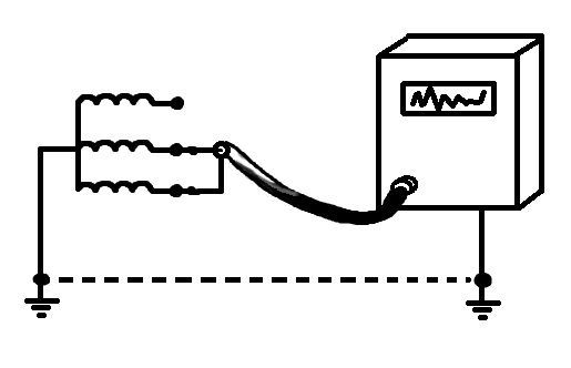
And here's where it gets more interesting. Few of the inhabitants know that in Russia there is a three-phase power supply. Visually, it looks like this: not one power wire, but three, and one more, called neutral or zero, come out of the transformer box in your microdistrict. The difference between the first three is that the current and voltage sinusoids in them are shifted relative to each other by 2π/3. This means that if in one wire the cycle is one third, then the second has just begun, and the third has not yet caught up. It is hard to imagine? You can take a picture like this:

This phenomenon is called phase shift.
One such wire and a neutral are connected to each apartment, connecting you to the ends of all three windings of your yard transformer and to the ground. However, you should also have a separate ground in order to divert static from the housings of household appliances.
From this figure, you can understand that the statement "there is no voltage at zero" is not entirely true. It will not be there when everyone in the apartments will have electrical appliances operating from three phases - then the load on them will be symmetrical. But few people would think of putting electric motors from industrial units in an apartment, and a symmetrical load is rare. Therefore, there is always some voltage in the neutral wire.
Phase search
At present, we can easily determine the phase wire using special devices. This simple operation is within the power of any person. We will do this in two ways - using an indicator screwdriver and a multimeter. And in the end, we'll talk about whether it is possible to find the phase and zero without devices and how to do it.
How to determine the indicator screwdriver
An indicator screwdriver is a device with a transparent handle, inside of which there is a capacitor bulb, and the end of the handle is a conductor. It looks like this:

The principle of operation of such an indicator is simple. You insert a screwdriver into the socket, and if you hit the phase and press the contact plate on the handle, then you increase the capacitance of the capacitor at the expense of your body - the neon light is on. The phase is easy to find. But zero, even if there is voltage in it - no. It does not happen there more than 60 V, and below this threshold, the indicator screwdriver will not show anything. This is not necessary: when the light bulb lights up only when it comes into contact with the phase, such a screwdriver is the best phase determiner.
More advanced versions of indicators (with LED, sound signal and batteries) are not helpers here: they will also show a lower voltage. If you show it, then even with the magnitude. And to determine this value, we better use a multimeter. But it is best to use such indicators to search for hidden wiring. There are more advanced devices for this purpose. Some of them react to the field created by alternating current, others to the metal in the wall. But all these devices have a different scope, which is beyond the scope of this topic.
Searching with a multimeter
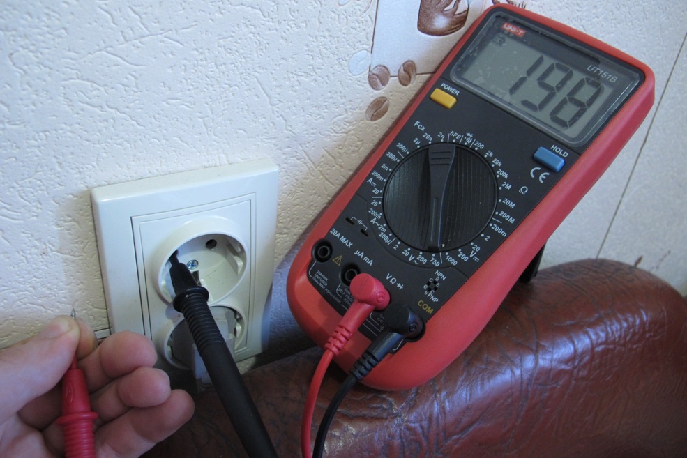
This is not difficult. To begin with, let's set the function on the switch of your tester (either this sector will be called ACV, or it will be V ~) with a limit above 220 V. For someone it will be 500, for someone 800. Testers are different. We insert the black probe into the common socket (COM is written next to it), and the red one into the socket for measuring current, voltage and resistance. It is not necessary to put it in a socket for working with a ten-ampere current, you most likely do not have it there. Then we insert both second ends of the probes into the socket holes. If it is working, the display will show the value of your voltage - from 220 to 230 V.
It remains to find out where the phase is. We insert the red probe into one of the outlet holes, and either hold the black one with our fingers or connect it to the ground, for example, to the battery central heating(Find where the paint has come off, or scrape off a bit). If you hit the phase, then the display will show an effective voltage of about 220 V. And if it is zero, then you will not see more than 60 V (more often - no more than 30 V).
Determination of phase and neutral wires for installing a three-phase socket
This situation can happen in the house with Soviet-made electric stoves. You have five wires, they are the same color, the socket will be unbalanced, and we need to know exactly where the three phases are, where is zero, and where is the ground. And this is important - all types of three-phase sockets we have are asymmetrical.
Here you need a little help. If we have 220 V between one phase and neutral, then between two phases with a shift of 120 degrees (2π / 3) 220 will need to be multiplied by the square root of three, and we will get an effective voltage of 380 V.
So we stock up on colored markers, a piece of paper and a pen, and begin to solve the puzzle. We mark the insulation with markers of different colors, look for the phases in the same way as in a conventional outlet, write the results on a piece of paper. It will be relatively easy to distinguish three phases. And then you need to find zero and ground. If grounding is done correctly, then the voltage in it will be zero, and there will be several tens of volts in the neutral.
To control, we measure the voltage between the phases. It should be 380 V, and between zero and each phase should be 220 V.
Another interesting use of a multimeter
The tester can be used to search for hidden wiring in an apartment if it is energized. Usually this can be done without it, if the wiring is carried out according to the rules. In this case, you can navigate by junction boxes. Worse, if you got the apartment after a home-grown renovation,  when everything superfluous was simply covered with plaster.
For wiring detection you will need a tester and a KP303 transistor (another field one is also possible).
Set the switch to about 200 kΩ. Insert the probes into the standard position (COM and universal jack) and connect their ends to the source and drain of the transistor. A wire antenna can be wound around the shutter. If there is a live wire in the wall, then it will create an electromagnetic field, albeit a small one, which will change the internal resistance of the transistor.
If there are no appliances
But what if you don’t have either a tester or an indicator screwdriver? How to determine the phase and zero without instruments? It turns out that this is possible.
True, before doing this, look at your shield: maybe you don’t have to do anything. If the house is new and the wiring in it is done according to the rules, then the wires can be identified by colors. So, zero is made blue, phase is any other color, and ground is yellow-green. Also pay attention for circuit breakers(like small switches): they must be in phase. If you unscrew the outlet and see the ground in its place, then most likely you didn’t confuse zero with the phase of the electrics either.
In general, there are household methods for diagnosing wiring, here are some of them:
- using a probe;
- with the help of potatoes;
- using old fuses and pliers;
- "with bare hands.
For obvious reasons, we will not discuss the last three.
Using a Probe
 A probe is an incandescent lamp in a cartridge with two wires brought out. It is not entirely ethical to advise this method of verification: this method is prohibited by the instructions. You should not use it in situations where you do not know how many phases are carried into the room and where everything turns on and off.
But sometimes you have to use a probe. For example, to distinguish zero from ground in the absence of sockets (we are considering a situation where sockets are not installed, and three wires stick out of the wall).
Recently, three-core wiring has been installed in residential premises. If electricians neglected the rules of color, you can distinguish where zero is and where the earth is with the help of a probe. To do this, you need to turn off one of the zeros in the shield, if you do not know which one is real, and check the performance of the future outlet. If you turn off zero, then the sockets will not work, and the light will not light up - the apartment ground is not connected to the circuit. And when the ground is disconnected, the light bulb will work.
What not to do
In fact, you already know the basic rules for working with wiring., but some I would like to repeat.
- Do not grab the multimeter probes by the bare parts. I hope I don't need to explain why.
- Some citizens have a habit of looking for hidden wiring with their bare hands. If you are one of those, there is no point in dissuading you. But you can give advice: do it with the back of your hand. If you get electrocuted, you will bounce off the wall, otherwise you risk not letting go of the exposed wire due to a cramp.
- Sometimes it is possible to measure resistance, rather than voltage, to indicate zero and phase. Be careful: when operating the tester in this mode, do not close the phase to ground, as a short circuit may occur.
When connecting various electrical devices (socket or switch), it is not necessary to take into account the polarity of the conductors. But what if the wiring used in the house is three-core and does not have a color marking, and the devices must be connected with a grounding conductor. To do this, there are several ways to check which of the wires is phase, zero or ground.
Determination of phase and zero without instruments
There are situations when, for the correct connection, it is necessary to find out which wire is the phase and which is zero. For example, to ensure the normal operation of the lighting fixture, a phase wire is cut into the gap (through the switch), and the zero wire is laid directly to lighting device. Currently, wiring in houses and apartments is laid with three-core wires, which are divided into three types.
Types of conductors:
- Phase;
- Zero;
- Grounding.
It is possible to distinguish the phase from zero in the wiring visually. But for this, one important condition must be met. Wiring in a house or apartment should be made using multi-colored conductors.
Phase conductor according to GOST rules, must be marked following colors: black, white, brown, purple, teal, red, grey, pink and orange.
Note! The most common colors found for marking phase wires are white, brown and pink.

The neutral conductor is easy to find, as it is always marked in blue. The ground wire is yellow-green.
It is worth noting that electricity, which is supplied to residential sectors, is variable, so the polarity of connecting electrical appliances does not matter. Proper connection is only important for DC equipment.
Phase and zero in the socket: how to determine with an indicator screwdriver
by the most in a simple way determining the phase conductor is to use a conventional indicator screwdriver. Currently, there are a huge number of these devices on the market.
Indicator types:
- With neon indicator;
- With the use of LEDs.
An indicator using a neon light bulb is made in the form of a dielectric case, inside of which there is a neon lamp with a resistor connected to it.
The design of LED indicators is presented in the form of a conventional screwdriver, inside which there is an LED, a microcircuit and several small batteries. These devices, having different characteristics, are similar in principle of operation.
It's important to know! It is possible to determine the phase conductor only if there is voltage in the electrical network.
In order to find the phase in the wiring, you must do the following. The voltage is removed from the conductor. This is done by turning off the circuit breaker in the electrical panel.
After that, the wires are stripped of insulation to a length of about 1 - 2 cm. The ends of the wire are pulled apart, this will help to avoid a short circuit between these conductors.
Voltage is applied to the wire by turning on the circuit breaker. Then, the metal part of the indicator is applied in turn to each and wires. The illuminated indicator will indicate the working phase in the wiring.
It should be noted that some devices, due to their design features, can be equipped with a metal plate at the top. To correctly determine the phase conductor, it is not necessary to touch it.
How to find the phase, zero and ground with a multimeter
If the phase conductor is easy to detect using an indicator screwdriver, then it is not possible to determine zero and ground with its help. Since these conductors do not affect the operation of the indicator in any way. In this case, it makes sense to use a multimeter.

To determine you need:
- Multimeter (tester);
- The presence of voltage 220 V.
The definition of each of the conductors should begin with the preparation of the device. Probes are connected to the plugs under the name COM and V.
If you need to find a phase wire, then for this, by turning the switch, on the multimeter, you must select the value of the measurement of alternating current in the range of more than 220 volts. After that, the probe that is connected to the socket with the name V, we touch all the conductors in turn. When touching the phase conductor, the display of the device will show values from 8 to 15 Volts. The neutral and ground conductor will not change these readings.
Note! When working on energized wiring, be sure to follow the safety rules.
After the phase conductor is found, you can start searching for the zero one. To do this, we touch the phase conductor with any probe of the multimeter, with the other we close the contact with any of the other conductors. The neutral conductor will be indicated by the value of 220 Volts that appears on the display of the device.
The third conductor will be the ground conductor. The readings on the display when touching the phase and ground wires are always lower than 220V.
Non-standard ways: how to determine the phase in the wiring
It should be borne in mind that these methods are unsafe. It is recommended to use them only if all necessary safety measures are observed.
Definition methods:
- Homemade control light;
- Potato.
To make a control light, you will need an ordinary cartridge, an incandescent lamp of any fashion and a meter wire. First of all, we clean the wire from insulation by about 1 cm. Next, we disassemble the cartridge and connect the ends of the wire to its terminals.

Then, in order not to damage the light bulb, it is necessary to strip the remaining ends of the wire to a length of 3 cm. We screw the light bulb into the prepared device. After that, turning off the voltage, we clean the ends of the conductor on which it is necessary to find the phase wire.
It is not necessary to twist the contacts of the control light with the wire, since free access to the conductor contacts is required.
Next, using any metal object, we clean a small area on metal surface water pipe. We apply voltage to the conductor and with one contact of the control we touch the stripped area on the pipe, and with the second one of the contacts of the wire. When touching the phase conductor, the lamp will light up.
Using a potato, check which of the phase wires is presented as follows. The device will require two meter-long wires and a 1 mΩ resistor. One of the wires must be mounted in a potato and attached to the pipe. The other wire is mounted in a potato with one of the ends, and the phase wire is searched for with the other. The appearance of browning on the potato will indicate the phase wire.
Understanding how to determine the phase and zero (video)
As practice shows, in most cases, the search for phase and neutral conductors in the AC electrical network is not necessary, since the polarity does not matter when connecting various household devices.